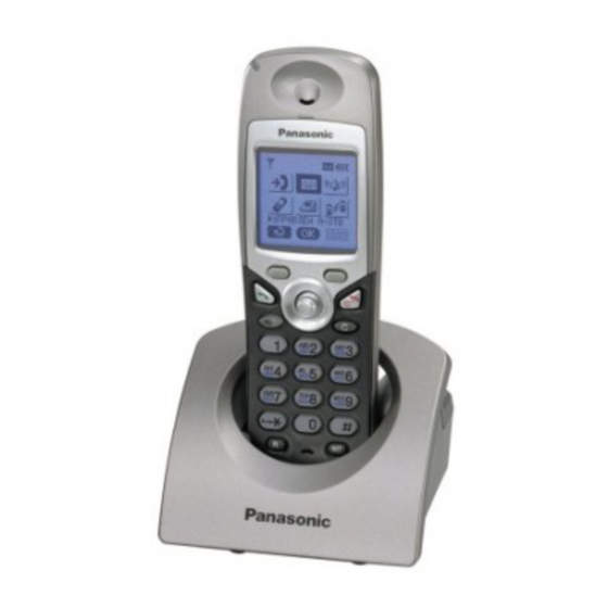
Summarization of Contents
ABOUT LEAD FREE SOLDER (PbF: Pb free)
Suggested PbF Solder
Details on recommended solder types and sizes for lead-free soldering.
How to recognize that Pb Free solder is used
Guidance on identifying PCBs manufactured with lead-free solder.
BATTERY
Battery Installation
Instructions for correct battery insertion and cover closure.
Battery Charge
Procedure for charging the cordless handset batteries before initial use.
Battery Information
Details on battery operating times for Ni-MH and Ni-Cd types.
Replacing the Batteries
Steps for replacing handset batteries and setting battery type.
LOCATION OF CONTROLS
Base Unit
Identification of controls and buttons on the base unit.
Cordless Handset
Identification of controls and buttons on the cordless handset.
Charger Unit
Identification of the charger unit's components and features.
Icons above SOFT KEYS
Explanation of icons displayed above the soft keys for base unit and handset.
SETTINGS
Connection
Guidelines for connecting the unit, including environment and location recommendations.
PIN Code
Procedures for setting and changing PIN codes for base unit and handset.
Reset the Settings
Steps to reset base unit and cordless handset settings to factory defaults.
Key Lock
How to lock and unlock the handset's keypad to prevent unintended use.
DISPLAY
Display Icons
Explanation of various icons displayed on the base unit and cordless handset.
Caller ID Service
How Caller ID service works and its display features.
Before Requesting Help (Troubleshooting)
Initial steps to take when experiencing problems with the apparatus.
OPERATIONS
Power ON/OFF
Instructions for turning the unit on and off.
Phonebook
Storing and managing caller information in the handset and base unit phonebooks.
Cordless Handset Registration to a Base Unit
Steps to register a cordless handset to the base unit.
DISASSEMBLY INSTRUCTIONS
Base Unit
Step-by-step guide for disassembling the base unit.
Cordless Handset
Step-by-step guide for disassembling the cordless handset.
Charger Unit
Step-by-step guide for disassembling the charger unit.
TROUBLESHOOTING GUIDE
Check Power
Procedure to verify if the AC adapter is properly connected and functioning.
Check Battery Charge
Steps to diagnose and resolve battery charging issues.
Check Link
Troubleshooting steps to verify the connection between the base unit and handset.
Check Cordless Handset Transmission
Steps to diagnose and resolve issues with handset transmission.
CHECK PROCEDURE (BASE UNIT)
Preparation
Lists required equipment and JIG/PC setup for base unit checks.
PC Setting
Instructions for configuring the PC and MS-DOS mode for testing.
CHECK PROCEDURE (CORDLESS HANDSET)
Preparation
Lists required equipment and JIG/PC setup for handset checks.
PC Setting
Instructions for configuring the PC and MS-DOS mode for testing.
ADJUSTMENTS (BASE UNIT AND CHARGER UNIT)
Adjustment (Base Unit)
Detailed procedures for adjusting base unit components after replacement.
Adjustment (Charger Unit)
Procedures for adjusting the charger unit components.
ADJUSTMENTS (CORDLESS HANDSET)
Adjustment (Cordless Handset)
Detailed procedures for adjusting cordless handset components after replacement.
RF SPECIFICATION
Base Unit
RF specifications for the base unit, including TX Power and Modulation.
Cordless Handset
RF specifications for the cordless handset, including TX Power and Modulation.
CIRCUIT OPERATION (BASE UNIT)
Outline
Overview of the base unit's circuit operation and key ICs.
Power Supply Circuit
Description of the power supply paths and components in the base unit.
Telephone Line Interface
Functionality of the telephone line interface circuit.
Transmitter/Receiver
Explanation of the base unit's transmitter and receiver blocks.
CIRCUIT OPERATION (CORDLESS HANDSET)
Outline
Overview of the cordless handset's circuit operation and key ICs.
Power Supply Circuit/Reset Circuit
Description of power supply and reset signals within the handset.
Charge Circuit
Explanation of the charging circuit operation for the cordless handset.
Battery Low/Power Down Detector
How battery voltage is monitored for low power or power down states.
Speakerphone and Headset Jack
Functionality of the speakerphone and headset jack circuits.
CIRCUIT OPERATION (CHARGER UNIT)
Power Supply Circuit
Description of the power supply circuit within the charger unit.
CPU DATA (BASE UNIT)
IC2 (BBIC)
Pin data and description for IC2 (BBIC) in the base unit.
CPU DATA (CORDLESS HANDSET)
IC1 (BBIC)
Pin data and description for IC1 (BBIC) in the cordless handset.
EEPROM LAYOUT (BASE UNIT)
Scope
Purpose of the section describing the EEPROM layout.
Introduction
Introduction to the base unit's serial EEPROM and default parameters.
EEPROM Layout
Detailed layout of the EEPROM contents for base unit configuration.
EEPROM LAYOUT (CORDLESS HANDSET)
Scope
Purpose of the section describing the EEPROM layout.
Introduction
Introduction to the handset's serial EEPROM and default parameters.
EEPROM contents
Detailed contents of the EEPROM for handset configuration.
HOW TO REPLACE FLAT PACKAGE IC
Preparation
Necessary tools and materials for replacing flat package ICs.
Procedure
Step-by-step instructions for soldering flat package ICs to the PCB.
Modification Procedure of Bridge
Method for modifying solder bridges on the PCB.
ACCESSORIES AND PACKING MATERIALS
KX-TCD530SLM
List of accessories and packing materials for the KX-TCD530SLM model.
KX-TCA151EXM
List of accessories and packing materials for the KX-TCA151EXM model.
TERMINAL GUIDE OF THE ICs, TRANSISTORS AND DIODES
Base Unit
Terminal guide for ICs, transistors, and diodes in the base unit.
Cordless Handset
Terminal guide for ICs, transistors, and diodes in the cordless handset.
REPLACEMENT PARTS LIST
Base Unit
List of replacement parts for the base unit, including cabinet and PCB components.
Cordless Handset
List of replacement parts for the cordless handset, including cabinet and PCB components.
Charger Unit
List of replacement parts for the charger unit, including cabinet and PCB components.
FOR SCHEMATIC DIAGRAM
Base Unit (SCHEMATIC DIAGRAM (BASE UNIT))
Schematic diagram for the base unit, detailing DC voltage measurements.
Cordless Handset (SCHEMATIC DIAGRAM (CORDLESS HANDSET))
Schematic diagram for the cordless handset, detailing DC voltage measurements.
CIRCUIT BOARD (CORDLESS HANDSET)
Component View
Component layout of the cordless handset circuit board.
Flow Solder Side View
Flow solder side layout of the cordless handset circuit board.
CIRCUIT BOARD (CHARGER UNIT)
Component View
Component layout of the charger unit circuit board.
Flow Solder Side View
Flow solder side layout of the charger unit circuit board.


Need help?
Do you have a question about the KX-TCA151EXM and is the answer not in the manual?
Questions and answers