Table of Contents
Advertisement
Quick Links
AUDIO/VIDEO MULTI-CHANNEL RECEIVER
SC-LX82
SC-LX72
THIS MANUAL IS APPLICABLE TO THE FOLLOWING MODEL(S) AND TYPE(S).
Model
Type
SC-LX82
SYXJ5
SC-LX72
SYXJ5
For details, refer to "Important Check Points for good servicing".
PIONEER CORPORATION
PIONEER ELECTRONICS (USA) INC. P.O. Box 1760, Long Beach, CA 90801-1760, U.S.A.
PIONEER EUROPE NV Haven 1087, Keetberglaan 1, 9120 Melsele, Belgium
PIONEER ELECTRONICS ASIACENTRE PTE. LTD. 253 Alexandra Road, #04-01, Singapore 159936
PIONEER CORPORATION
Power Requirement
AC 220 V to 230 V
AC 220 V to 230 V
4-1, Meguro 1-chome, Meguro-ku, Tokyo 153-8654, Japan
2009
SC-LX82
T-ZZV JULY
ORDER NO.
RRV3967
Remarks
2009 Printed in Japan
Advertisement
Table of Contents

Related Manuals for Pioneer SC-LX72


Summarization of Contents
SAFETY INFORMATION
WARNING: LEAD IN SOLDER
California Proposition 65 warning about lead in solder and chemicals.
NOTICE (FOR CANADIAN MODEL ONLY)
Identifies fuse symbols and requirements for replacement parts for Canadian models.
REMARQUE (POUR MODÈLE CANADIEN SEULEMENT)
French version of the notice regarding fuse symbols and replacement parts.
1. SAFETY PRECAUTIONS
Guidelines for service technicians to ensure customer and technician safety during repairs.
LEAKAGE CURRENT CHECK
Procedure to measure leakage current to prevent electric shock hazards.
[Important Check Points for Good Servicing]
1. Product safety
Conforming to regulations and maintaining a safe servicing environment.
2. Adjustments
Procedures for maintaining original product performance through optimum adjustments.
3. Lubricants, Glues, and Replacement parts
Guidance on using specified lubricants, glues, and replacement parts.
4. Cleaning
Procedures for cleaning parts to restore performance, such as optical pickups.
5. Shipping mode and Shipping screws
Instructions for setting shipping mode or installing shipping screws before shipment.
1. SERVICE PRECAUTIONS
1.1 NOTES ON SOLDERING
Precautions for using lead-free solder and appropriate soldering irons.
1.2 NOTES ON REPLACING PARTS
Identification of parts that require replacing the entire assembly when defective.
1.3 CAUTION
Important precautions before starting diagnosis, including discharging and ground points.
2. SPECIFICATIONS
2.1 SPECIFICATIONS
Detailed technical specifications for the audio/video receiver.
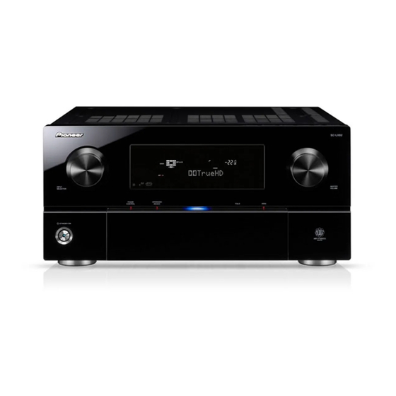
2.2 PANEL FACILITIES
[1] Front Panel
Identification and function of controls and indicators on the front panel.
3. BASIC ITEMS FOR SERVICE
3.1 CHECK POINTS AFTER SERVICING
Procedures and check points to confirm after servicing to ensure product quality.
4. BLOCK DIAGRAM
4.1 OVERALL WIRING DIAGRAM
Diagram illustrating the overall wiring connections between major assemblies.
5. DIAGNOSIS
5.1 DIAGNOSIS FLOWCHART
Flowcharts for troubleshooting various functional blocks like DSP and HDMI/DVC.
5.2 CIRCUIT DESCRIPTION
[1] Protection Circuit Process List
Details of protection circuit functions, detection methods, and status indications.
E DIGITAL MAIN ASSY
DIGITAL MAIN Power Supply Failure Detection
Procedures for detecting and diagnosing power supply failures in the digital main circuit.
6. SERVICE MODE
6.1 TEST MODE
Procedures for entering test mode to display protection history and status.
Disassembly [1] Exterior Section
[1-1] Center beam V1, Left beam 81
Instructions for removing the center beam V1 and left beam 81.
[2] PCB Assys
[2-1] COMPONENT Assy
Procedures for removing the COMPONENT Assy, including disconnecting cables and connectors.
8. EACH SETTING AND ADJUSTMENT
8.1 HOW TO UPDATE FIRMWARE
Step-by-step guide for updating the unit's firmware via USB memory.
[3] Network Firmware Update Procedure
[Necessary Tools]
List of required software and hardware for network firmware updates.
[Connections]
Diagrams illustrating network connection methods for firmware updates.
[When the PC and AV amplifier are connected via a DHCP router]
How to Confirm the IP Address
Procedure to confirm and note the AV amplifier's IP address for network connection.
11. PCB CONNECTION DIAGRAM
11.1 AUDIO ASSY
PCB layout and connector pin assignments for the AUDIO Assy.
12. PCB PARTS LIST
LIST OF ASSEMBLIES
Comprehensive list of all assemblies with their part numbers for SC-LX82 and SC-LX72.
Need help?
Do you have a question about the SC-LX72 and is the answer not in the manual?
Questions and answers