Table of Contents
Advertisement
Quick Links
SW1001
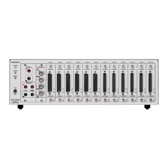
SW1002
SWITCH MAINFRAME
Read carefully before use.
Keep for future reference.
When using the instrument for the
first time
Safety Information
Measurement Flowchart
Preparation for Measurements
Jan. 2022 Revised edition 4
SW1001A961-04 22
p.4
p.12
p.13
-
H
01
HIOKI SW1001A961-04
Instruction Manual
Troubleshooting
Maintenance and Service
Error display and troubleshooting
p.125
p.126
EN
*600510224*
Advertisement
Table of Contents
Troubleshooting

Related Manuals for Hioki SW9002

Summarization of Contents
Hioki SW1001/SW1002 Switch Mainframe Overview
Product Overview
Describes the module type switching system for battery measurements.
Key Features of Switch Mainframe
Highlights error reduction and instrument switching capabilities.
Parts Identification and Functionality
Identifies and describes front and rear panel components of the device.
System Block Diagram
Illustrates the device's configuration and data flow.
Glossary of Terms
Defines key terms used in the manual.
Measurement Process Flowchart
Outlines the steps for device installation, connection, and measurement.
Safety Information and Usage Notes
Usage Notes and Precautions
Provides essential guidelines for safe and proper device operation.
Preparation for Device Measurements
Instrument Connection and Control
Details connecting instruments and controlling the device via PC or PLC.
Connection Cable Setup
Details on connecting the device to instruments using specific cables.
Communication Setting Mode Configuration
Explains how to select fixed or user-defined communication settings.
Power Cord Connection
Steps for safely connecting the power cord to the device.
Device Power On/Off Operations
Instructions on how to turn the device's power on and off.
Device Initialization Behavior
Describes the device's state and settings upon power-up.
Channel Switching Operations
Pre-Measurement Inspection
Verifies device and cable condition for safe operation.
Channel Switching System Overview
Explains the internal analog bus connection via module channel relays.
Channel Switching Procedure
Details selecting connection methods, shields, and channels.
Channel Switching Operation Flow
Describes the sequence and timing of channel switching.
Dual Instrument Measurement Setup
Explains how to perform measurements using two instruments simultaneously.
Measurement Precautions
Provides safety and operational advice for various measurement conditions.
Channel Delay Functionality
Describes setting delay times for channel switching operations.
Scan Functionality for Sequential Measurement
Scan Function Overview
Introduces scanning for sequential channel switching and measurement.
Scan Channel Configuration
Details registering channels in a scan list for sequential measurement.
Scan Operation Trigger Source Setup
Explains how to set the trigger source (STEP) for scan operations.
Scan Operation Execution
Describes how scanning starts, advances, and completes via signals or commands.
Resetting Scan Operations
How to stop and reset the scan operation.
Scan Measurement Example with EXT. I/O
Demonstrates scan measurement using SW1001 and BT3562A via EXT. I/O.
Additional Device Functions
Device Status Check via Software
Describes using free software to check module and relay status.
Device Initialization Settings
Default Initialization Settings
Lists settings initialized at shipment or by command.
External Control via EXT. I/O
External Control Workflow
Outlines the steps for setting up external control.
NPN/PNP Output Mode Selection
How to switch the EXT. I/O circuit for NPN or PNP output.
EXT. I/O Terminal Connection
Details connector types, pin assignments, and signal functions.
External Control Timing Charts
Illustrates timing for channel switching and scan reset operations.
EXT. I/O Internal Circuit Diagrams
Shows circuit diagrams for NPN and PNP settings.
Device Communication Interfaces
Communication Interface Overview
Introduces LAN, USB, and RS-232C interfaces for device control.
Communication Setting Mode Configuration
Explains selecting fixed or user-specified communication settings.
LAN Communication Setup
Details networking, connection, and communication condition settings.
USB Communication Setup
Instructions for installing USB drivers and connecting via USB.
RS-232C Communication Setup
Guide for connecting and setting up RS-232C communication.
Command Forwarding Function
How to forward commands to instruments via the device.
Communication Message Formatting
Explains message types, formats, syntax, and terminators.
SW1001/SW1002 Technical Specifications
General Specifications
Lists operating environment, power, dimensions, and mass.
Input/Output and Measurement Specifications
Details slot counts, analog bus, terminals, and input voltage limits.
Functional Specifications
Covers channel switching, connection, delay, shield, and scan functions.
Interface Specifications (LAN, USB, RS-232C, EXT. I/O)
Provides detailed specifications for each communication interface.
Maintenance and Service Information
Troubleshooting Guide
Lists common symptoms, causes, solutions, and references for issues.
Device Error Number Reference
Provides a list of error codes, descriptions, and solutions.
Repair and Inspection Guidelines
Information on replaceable parts and their recommended replacement cycles.
Multiplexer Module Details
SW9001 Multiplexer Module Specs
Features and specifications for the 2-wire/4-wire multiplexer module.
SW9002 Multiplexer Module Specs
Features and specifications for the 4-terminal pair multiplexer module.
Combined Accuracy Calculation Examples
Demonstrates calculating combined accuracy with connected instruments.
Appendix and Supplementary Information
Measurement Cable Wiring Diagrams
Provides wiring diagrams and specifications for measurement cables.
Relay Contact Welding Risks
Explains potential short circuits caused by relay contact welding.
Rack Mounting Options
Details on attaching rack mount brackets for installation.
Outline Dimensional Drawings
Provides dimensional drawings for SW1001 and SW1002.
Need help?
Do you have a question about the SW9002 and is the answer not in the manual?
Questions and answers