Table of Contents
Advertisement
Quick Links
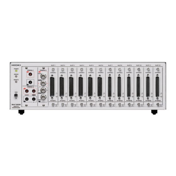
SW1001
SW1002
SWITCH MAINFRAME
Read carefully before use.
Keep for future reference.
When using the instrument for the
first time
Safety Information
Measurement Flowchart
Preparation for Measurements
Jan. 2022 Revised edition 4
SW1001A961-04 22
p.4
p.12
p.13
-
H
01
HIOKI SW1001A961-04
Instruction Manual
Troubleshooting
Maintenance and Service
Error display and troubleshooting
p.125
p.126
EN
*600510224*
Advertisement
Table of Contents
Troubleshooting

Subscribe to Our Youtube Channel
Summary of Contents for Hioki SW9001
- Page 1 When using the instrument for the Troubleshooting first time p.125 Safety Information Maintenance and Service p.12 p.126 Measurement Flowchart Error display and troubleshooting p.13 Preparation for Measurements Jan. 2022 Revised edition 4 *600510224* SW1001A961-04 22 HIOKI SW1001A961-04...
- Page 2 HIOKI SW1001A961-04...
-
Page 3: Table Of Contents
Measurement between Two .....61 Communication condition settings Instruments ..........32 ....62 Setting LAN communications ......63 Precautions for Measurement Connecting the LAN cable ....35 USB Interface ........64 Channel Delay Function ......37 ......64 Installing the USB driver ......65 Connecting the USB cable SW1001A961-04 HIOKI SW1001A961-04... - Page 4 Contents RS-232C Interface ........66 Multiplexer Module ....66 Connecting the RS-232C cable Setting RS-232C communications .....68 11.1 SW9001 Multiplexer Module ..68 Setting the controller (PC, PLC, etc.) (2-wire/4-wire) ........129 Communication Command Features ..........129 Forwarding Function ......69 .........129 Specifications Communication Method .......71 Switching wiring diagram ......133...
-
Page 5: Introduction
Introduction Introduction Thank you for purchasing the Hioki SW1001, SW1002 Switch Mainframe. To obtain maximum performance from the device over the long term, be sure to read this manual carefully and keep it handy for future reference. With the optional multiplexer module (hereafter referred to as “module”) installed on this device, the input of multiple channels can be switched to one or two measuring instruments (hereafter referred to as simply “instrument”). -
Page 6: Confirming Package Contents
* The latest version can be downloaded from our website. Options The following options are available for the device. Contact your authorized Hioki distributor or reseller when ordering. The options are subject to change. Visit our website for updated information. Module... - Page 7 Maximum rated voltage*: CAT III: 1000 V CAT IV: 600 V * Do not input voltage exceeding the rating of this device and the instrument. Communications cable Model 9642 Model L1002 Model 9637 LAN Cable USB Cable (A-B) RS-232C Cable (9pin-9pin/1.8 m) HIOKI SW1001A961-04...
-
Page 8: Safety Information
• Before using the device the first time, verify that it operates normally to ensure that no damage occurred during storage or shipping. If you find any damage, contact your authorized Hioki distributor or reseller. This device is designed to measure voltages of 60 V or lower. Do not input voltages over 60 V or measure locations exceeding 60 V from the ground potential. - Page 9 Prevent the voltage potential difference of the entire system from exceeding 60 V DC. The measurement connector frame of the module is connected to the casing (metal) of the device as well as the protective ground terminal of the power inlet (conductive). HIOKI SW1001A961-04...
- Page 10 • Keep discs inside a protective case and do not expose to direct sunlight, high temperature, or high humidity. • Hioki is not liable for any issues your computer system experiences in the course of using this disc. HIOKI SW1001A961-04...
-
Page 11: Overview
For example, you can connect a BT3562A and DM7276 to the device and use it to switch between internal resistance measurement and high-precision OCV measurement. Protection against short circuit with fuses To protect batteries to be measured if a short circuit occurs in a channel, a protective fuse is built into each channel. HIOKI SW1001A961-04... -
Page 12: Parts Names And Functions
1 8 Measurement cable connector module. For more details, see the chapter for the p. 1 34 multiplexer module. p. 1 41 terminal Ground for the device. Connected to the ground. p. 3 6 HIOKI SW1001A961-04... - Page 13 Serial number – indicate the month of manufacture. Required for production control. Do not peel off the label. MAC address MAC address of the LAN. p. 1 05 HIOKI SW1001A961-04...
-
Page 14: Block Diagram
Block Diagram 1.4 Block Diagram The configuration of this device is shown in the following block diagram. Switch Mainframe Internal analog bus Terminal Module Module EXT. I/O Connection cable Measurement cable PC/PLC Instrument Measuring object HIOKI SW1001A961-04... -
Page 15: Glossary
Scan Switches the pre-registered channel (scan list) in sequence. p. 3 9 Connecting the instrument and this device using EXT. I/O enables the channel to be switched and trigger measurement to be performed automatically. HIOKI SW1001A961-04... -
Page 16: Measurement Flowchart
Sending a measurement command to the instrument. Receiving measurement results. • For information on the measurement processing and receiving measurement results, see the instruction manual of the instruments to be used. Ending the measurement Turning off the power. (p. 2 3) HIOKI SW1001A961-04... -
Page 17: Preparation For Measurements
EXT. I/O interface. You can also acquire measured values by using the instrument’s data output function (to automatically send measured values) or memory function. See: “4 Scan Function” (p. 39) SW1001 LAN/USB/RS-232C EXT. I/O Instrument LAN/USB/RS-232C HIOKI SW1001A961-04... - Page 18 SW1001 Instrument LAN/USB/RS-232C RS-232C only EXT. I/O Connecting two instruments You can perform measurement by connecting two instruments to the device. See: “3.5 Measurement between Two Instruments” (p. 32) SW1001 LAN/USB/RS-232C Instrument 1 LAN/USB/RS-232C Instrument 2 LAN/USB/RS-232C HIOKI SW1001A961-04...
-
Page 19: Installing The Module
Loosen the two screws (M3 × 6 mm) and then remove the blank panel. Blank panel Screw Store the blank panel and screws. (M3 × 6 mm) You need the screws when using the device after removing the module. HIOKI SW1001A961-04... -
Page 20: Removing The Module
Tighten the two screws to secure the module in place. Screw 2.3 Removing the Module Required items: Phillips screwdriver (No. 2), antistatic gloves Front Touch the terminal with bare hands. Wear antistatic gloves. Rear Turn off the device. HIOKI SW1001A961-04... - Page 21 Loosen the two screws. Screw Pull out the module. Attach the blank panel and tighten the two screws (M3 × 6 mm) to secure the Blank panel panel. Screw (M3 × 6 mm) HIOKI SW1001A961-04...
-
Page 22: Connecting The Measurement Cable
Disconnect Tip of the probe Front Connect the measurement cable connector to the module’s connector. Secure the measurement cable connector using the screws. For information on connecting the measuring object, see the instruction manual of each instrument. HIOKI SW1001A961-04... -
Page 23: Connecting The Connection Cable
Front Select the terminal and connection cable to be connected based on the instrument to be connected. Instrument Connection Connection Model Terminal Module example cable method SW9001 Voltmeter DM7276 TERMINAL 1 L4930 2-wire SW9002 Battery tester BT3562A TERMINAL 2 L2108... -
Page 24: Terminal 1
Connect the connection cable so that the red mark of the device and the mark of the red lead wire match and the black mark of the device and the mark of the black lead wire match. Front Black Connect the other end of the connection cable to the instrument. HIOKI SW1001A961-04... -
Page 25: Terminal 3
Connect the other end of the connection cable to the instrument. Instrument terminal Connection cable terminal BT4560 IM3590 SOURCE-H (red) SOURCE-H (red) Hcur SENSE-H (red) SENSE-H (red) Hpot SENSE-L (black) SENSE-L (black) Lpot SOURCE-L (black) SOURCE-L (black) Lcur HIOKI SW1001A961-04... -
Page 26: Setting The Communication Setting Mode
> Transmission speed Reference: “(8) RS-232C settings” (p. 103) • LAN :SYSTem:COMMunicate:LAN:IPADdress < > IP address :SYSTem:COMMunicate:LAN:SMASk < > Subnet mask :SYSTem:COMMunicate:LAN:GATeway < > Gateway address :SYSTem:COMMunicate:LAN:CONTrol < > Port No. :SYSTem:COMMunicate:LAN:UPDate Reference: “(9) LAN settings” (p. 103) HIOKI SW1001A961-04... -
Page 27: Connecting The Power Cord
When an error occurs, the ERROR lamp on the front lights up. If an error occurs during self-test, communications and control using EXT. I/O become disabled. Front HIOKI SW1001A961-04... -
Page 28: When The Power Is Turned On
Scan settings Settings are saved with the settings backup command. Channel delay settings Settings are saved with the settings backup command. Communication settings Settings are saved with the settings backup command. See: “Backing up settings” (p. 1 05) HIOKI SW1001A961-04... -
Page 29: Channel Switching
Thoroughly read "Usage Notes" (p. 4) beforehand. 3.1 Inspection before Measurement Verify that it operates normally to ensure that no damage occurred during storage or shipping. If you find any damage, contact your authorized Hioki distributor or reseller. Inspecting the device and peripheral devices Check item... -
Page 30: Checking For Relay Contact Welding
2, SOURCE L TERMINAL 3, SOURCE H shield TERMINAL 3, SOURCE L shield The connector is for the SW9001. Tester Check that the terminal of the shorted module and the above points of the terminal on the main frame are not electrically connected. -
Page 31: Overview Of Channel Switching
TERMINAL 2 (4-terminal banana terminal) and TERMINAL 3 (BNC terminal) use a common analog bus (electrically connected). CAUTION Do not connect TERMINAL 2 TERMINAL 3 to the instrument at the same time. Doing so may damage the instrument. HIOKI SW1001A961-04... -
Page 32: Procedure For Switching The Channel
Return Return: CH1 to CH6 TERMINAL 3 Sense Sense: CH1 to CH6 If the SW9001 is set to 4-wire and the 4- selection channel is “n”, the following signals are used wire in pairs. Source: CH n Sense: CH (n+11) -
Page 33: Switching The Shield
Not connected SW9002 TERMINAL 1, LOW terminal TERMINAL 3, sense shield terminal For the SW9001, the [TERMINAL 1, LOW terminal + TERMINAL 3, sense shield terminal] shielding connection destination terminal should only be used when connecting a BT3562, BT3562A series (BT3562, BT3563, BT3561A, BT3562A, BT3563A) and DM7275 series (DM7275, DM7276) at the same time when the DM7275/DM7276 contact check function is not operating properly. -
Page 34: Selecting The Channel
Waits for the present operation to complete and returns the value 1. The subsequent command will be made to wait until this command completes. Confirming SLOT 1 Select CH7 of and wait for switching operation to complete. :CLOS 107 example *OPC? (receive a response = switching operation complete) HIOKI SW1001A961-04... -
Page 35: Channel Switching Operation
After the channel relay is closed and then the settling time that is automatically set and the channel delay time that is specified by the customer elapse, channel switching operation is complete and the CLOSE output signal of EXT. I/O is turned on (pulse output at the set pulse width). HIOKI SW1001A961-04... -
Page 36: Measurement Between Two Instruments
Measurement Connection Instrument Module Channel selection Terminal to be used item method SLOT 1, CH1 SLOT 1, CH2 Internal BT3562A SW9001 4-wire SLOT 1, CH3 TERMINAL 2 resistance ⁞ SLOT 1, CH8 SLOT 1, CH12 SLOT 1, CH13 DM7276 SW9001... - Page 37 TERMINAL Connection Instrument Measurement item Module Channel selection Terminal to be used method SLOT 1, CH1 SLOT 1, CH2 BT3562A Internal resistance SW9001 4-wire SLOT 1, CH3 TERMINAL 2 ⁞ SLOT 1, CH8 SLOT 1, CH12 SLOT 1, CH13 DM7276...
- Page 38 Check that the channel relay has been closed. [SW1001] OPC? Receive a response “1” to the query. [DM7276] :READ? Execute single measurement using DM7276. [DM7276] +00.257139E+00 Receive measured values. [SW1001] :CLOSE 202 Select the next CH2. (Repeat until CH8.) HIOKI SW1001A961-04...
-
Page 39: Precautions For Measurement
If this happens, allow a few seconds to a few minutes for the stabilization time to check that the measured value stabilizes. For measurement Ω of high-resistance (100 k or more) components, measured values may not be stable due to the effect of noise, including hum. HIOKI SW1001A961-04... - Page 40 When attaching the module to the main frame, be sure to secure the panel using screws. If the panel cannot support the load when a vertical load is applied to the main frame, the module board is stressed and may malfunction. HIOKI SW1001A961-04...
-
Page 41: Channel Delay Function
Communication command :SYSTem:MODule:DELay < slot No. >,< delay time 0 to 9.999[ ]> Setting procedure Setting SLOT 1 SLOT 2 Set the channel delay time for to 0.01 sec. and for to 0 sec. :SYST:MOD:DEL 1,0.01 example :SYST:MOD:DEL 2,0 HIOKI SW1001A961-04... - Page 42 Channel Delay Function HIOKI SW1001A961-04...
-
Page 43: Scan Function
• The EOM signal from the instrument may cause scan measurement to resume even if it has been :ABORt stopped using the SCAN_RESET signal or the command. For the EXT. I/O signal, see "Signal Functions" (p. 5 2). HIOKI SW1001A961-04... -
Page 44: Setting The Scan Channel
External trigger. Scanning is performed with the SCAN input signal of EXT. I/O or the *TRG command. Scan operation moves along the steps every time the trigger is input. Setting Set to proceed with the next step every time the external trigger is input. :TRIG:SOUR STEP example HIOKI SW1001A961-04... -
Page 45: Scan Operation
The following commands are disabled during scanning. • Setting the connection method • Setting the shield switching • Channel switching • Setting the channel delay • Setting the scan list • Setting concerning the EXT. I/O • Channel control due to CLOSE command HIOKI SW1001A961-04... -
Page 46: Resetting Scan Operation
Resetting Scan Operation 4.5 Resetting Scan Operation Scanning is reset and stopped by the SCAN_RESET signal of EXT. I/O or the communication :ABORt command. All channel relays are opened and goes back to the beginning of the scan list. HIOKI SW1001A961-04... -
Page 47: Scan Measurement Example
Set data output to on TRIG BT3562A SW1001 SCAN SW1001 setting Connection method: 4-wire Scan list registration Wiring diagram SW1001 Start scanning *TRG Scan input signal or command BT3562A Receive measured values. Measured value received for all channels Scan measurement complete HIOKI SW1001A961-04... - Page 48 Scan Measurement Example HIOKI SW1001A961-04...
-
Page 49: Other Functions
The following items can be checked using the free software for the SW1001 series (downloaded from our website). • Module information of each slot Slot position, model, serial number, and opening/closing frequency of each relay Use the information as a reference for the relay lifetime. HIOKI SW1001A961-04... - Page 50 Checking the Device Status HIOKI SW1001A961-04...
-
Page 51: Initialization
Item Initialization description Backup Channel relay All relays open – Bus relay All relays open – EXT. I/O CLOSE output signal – SW9001: 2-wire Connection method SW9002: 4-terminal pair SW9001: TERMINAL 1, LOW terminal Shield switching SW9002: TERMINAL... - Page 52 Initialization Settings HIOKI SW1001A961-04...
-
Page 53: External Control (Ext. I/O)
Signal output or input 7.1 External Control Flow Check the I/O specifications of the instrument and external device to be connected. Setting NPN/PNP in the device (p. 5 0). Connecting the device and the external device (p. 5 1). HIOKI SW1001A961-04... -
Page 54: Switching Between Sinking Current (Npn) And Sourcing Current (Pnp)
EXT. I/O MODE change-over switch settings Device input circuit Supports sinking output. Supports sourcing output. Device output circuit Non-polar Non-polar ISO_5 V output +5 V output -5 V output Rear Left: Sinking current (NPN) Right: Sourcing current (PNP) HIOKI SW1001A961-04... -
Page 55: Connection
– ISO_5V – Isolated power supply +5 V (−5 V) output – CLOSE Channel closing complete Pulse (Reserved) – – SCAN_RESET Resets scan operation. Edge (Reserved) – – ISO_COM – Isolated power supply common – (Reserved) – – HIOKI SW1001A961-04... -
Page 56: Signal Functions
Set the BT3562A to the external trigger mode. SW1001 (SW1002) BT3562A Rear Rear 5 4 3 2 1 4: CLOSE 1: TRIG 1: SCAN 28: EOM 8: ISO_COM 27: ISO_COM 9 8 7 6 10 9 8 7 6 5 4 3 2 1 HIOKI SW1001A961-04... -
Page 57: Timing Chart
If the next channel is closed before the CLOSE signal pulse reaches the set pulse width, CLOSE signal pulse will automatically turn off. The SCAN input signal is not valid while switching channels (until the CLOSE signal is output). HIOKI SW1001A961-04... - Page 58 Time SCAN signal pulse width 1 ms or longer Relay settling time (when it is opened) SW9001: 5 ms, SW9002: 5 ms Relay settling time (when it is closed) SW9001: 5 ms, SW9002: 5 ms Channel delay time (user setting)
-
Page 59: Internal Circuit Configuration
Output SCAN SCAN_RESET Common EXT. I/O MODE Internal isolated selector power supply PLC, etc. Ω Input CLOSE Zener voltage 30 V ISO_COM Common Internal isolated common 30 V max. (It is isolated from the ground for the device.) HIOKI SW1001A961-04... -
Page 60: Electrical Specifications
100 mA External power supply None input Insulation Floating from the protective grounded potential and the measurement circuit Insulation rating Voltage between the module and ground: 50 V DC, 30 V AC rms, 42.4 V AC peak or less HIOKI SW1001A961-04... -
Page 61: Connection Examples
Input Input ISO_COM ISO_COM Connection to the switch Connection to the relay This device This device Input Output Input Output ISO_COM Common ISO_COM Common Connection to the PLC output (NPN output) Connection to the PLC output (PNP output) HIOKI SW1001A961-04... - Page 62 Negative-true logic output ISO_COM Wired-OR This device This device Output Input Output Input 50 mA max. 50 mA max. ISO_COM Common ISO_COM Common Connection to the PLC input Connection to the PLC input (minus common input) (plus common input) HIOKI SW1001A961-04...
-
Page 63: Communication Function
Refer to "2.6 Setting the Communication Setting Mode" (p. 22) to set the communication setting mode. Specify communication settings according to the interface to be used. See: "8.3 LAN Interface" (p. 60) "8.4 USB Interface" (p. 64) "8.5 RS-232C Interface" (p. 66) HIOKI SW1001A961-04... -
Page 64: Lan Interface
When a program is created and the device is connected to the communication command port via TCP, the device can be controlled using communication commands. Flow of preparations Set the communication conditions of the device (p. 6 1). Connect the LAN cable (p. 6 3). HIOKI SW1001A961-04... -
Page 65: Communication Condition Settings
The addresses shown below are recommended if there is no administrator or you are responsible for setting. Setting example: IP address Set sequential IP addresses as shown below. 192.168.0.1 First device: 192.168.0.2 Second device: 192.168.0.3 Third device: 192.168.0.4 ↓ Subnet mask: 255.255.255.0 Gateway: Communication command port number: HIOKI SW1001A961-04... -
Page 66: Setting Lan Communications
PC settings. For one-to-one connection between the device and PC or when no gateway is used Set the IP address to 0.0.0.0. Communication Specify the TCP/IP port No. used for connecting communication commands. command port No. HIOKI SW1001A961-04... -
Page 67: Connecting The Lan Cable
If the green LED on the LAN connector is not lit even after the device has been connected to the LAN, the device or connection device may be malfunctioning or the LAN cable may have a broken wire. HIOKI SW1001A961-04... -
Page 68: Usb Interface
Ignore the message and continue the installation procedure. Uninstallation procedure Uninstall the USB driver when it is no longer required. Click [Control Panel] [Uninstall a program], and then delete [HIOKI USB CDC Driver]. HIOKI SW1001A961-04... -
Page 69: Connecting The Usb Cable
USB Interface Connecting the USB cable Thoroughly read "Before connecting the communications cables" (p. 6 ) beforehand. Recommended cable: Hioki model L1002 USB Cable (A-B) Rear Type B USB interface of the PC HIOKI SW1001A961-04... -
Page 70: Rs-232C Interface
Data Terminal Ready ON level (+5 V to +9 V) fixed Signal Ground Data Set Ready Not connected Request to Send ON level (+5 V to +9 V) fixed Clear to Send Not connected Ring Indicator Not connected HIOKI SW1001A961-04... - Page 71 Use a D-sub 9-pin female/female crossover cable. Connect the HOST RS-232C connector of the device and the COM port of the PC. Recommended cable: Hioki modeI 9637 RS-232C cable (9pin-9pin/1.8 m) Cross connections D-sub 9-pin female D-sub 9-pin female Device side PC side Pin No.
-
Page 72: Setting Rs-232C Communications
(Set the speed based on the device settings.) Data bit length Stop bit Parity check None Flow control None Protocol Non-procedure IMPORTANT Communications may not be established at the high transmission speed (baud rate) depending on the PC. Lower the transmission speed in that case. HIOKI SW1001A961-04... -
Page 73: Communication Command Forwarding Function
Before receiving data for the first time, send the query and receive the response in order to clear the device’s receive buffer. Transferring is done by row unit and buffer is approx. 128 byte of both sending and receiving. Binary data is incompatible. HIOKI SW1001A961-04... - Page 74 Sending a query to the instrument will result in a timeout error if the set timeout time elapses before a response is received from the instrument. Timeout can be set by the command below. :SYSTem:COMMunicate:FORWard:TIMeout < Time > Time: Timeout time (s) HIOKI SW1001A961-04...
-
Page 75: Communication Method
Requests for responses relating to results of operation or measurement, or the state of device settings Example: Request for the present measurement range :ROUT:CLOSE? Header portion Question mark See: "Headers" (p. 7 2), "Separators" (p. 7 3), and "Data formats" (p. 7 4) HIOKI SW1001A961-04... - Page 76 As shown by the following examples, when a query is formed by appending a question mark ( ) after a program header, it is recognized as a query. STB? Example: :SYSTem:ERRor? HIOKI SW1001A961-04...
- Page 77 In a message consisting of both a header and data, the header is separated from the data by a space. :SCAN:ADD 101 Example: Space (3) Data separator In a message containing multiple data items, commas ( ) are required to separate the data items from one another. :SYST:MOD:WIRE:MODE 1,WIRE2 Example: Comma HIOKI SW1001A961-04...
- Page 78 The term “NRf format” includes all three of the above numeric decimal formats. The device accepts NRf format data. The format of response data is specified for each command, and the data is sent in that format. :STAT:QUES:ENAB 106 Example: :IO:PULSE:TIME 0.001 HIOKI SW1001A961-04...
- Page 79 A colon ( ) is not required at the start of the header of a simple or compound command. However, to avoid confusion with abbreviated forms and operating mistakes, Hioki recommends to always place a colon ( ) at the start of a header.
-
Page 80: Output Queue And Input Buffer
When using the RS-232C interface, data may be lost in the event of a buffer overrun. When using the LAN or USB interface, operation will enter a wait state once the buffer becomes full and continue in that state until the buffer is empty. HIOKI SW1001A961-04... -
Page 81: Status Byte Register
Required items are selected from this information by masking with the Service Request Enable Register. When any bit selected by the mask is set, bit 6 (MSS; the Master Summary Status) of the Status Byte Register is also set, which generates an SRQ (Service Request) message and dispatches a service request. HIOKI SW1001A961-04... - Page 82 Reset using to output error information. Bit 1 – Unused Bit 0 – Unused Service Request Enable Register (SRER) Setting a bit of this register to “1” enables the corresponding bit of the Status Byte Register to be used. HIOKI SW1001A961-04...
-
Page 83: Event Registers
Each bit is not cleared even if the query result is returned. :STATus:OPERation:EVENt? When 1 is set for each bit, the status is retained until the query result is returned. :STATus:OPERation:ENABle :STATus:OPERation:ENABle? HIOKI SW1001A961-04... - Page 84 • When data in the output queue has been lost Not used by this device. Bit 1 (Unused) Request control Operation complete Bit 0 • Execution of an command. • Completion of operations of all messages up to the command. HIOKI SW1001A961-04...
- Page 85 2 bit 1 bit 0 Logical sum & & & & & & & & bit 7 bit 6 bit 5 bit 4 bit 3 bit 2 bit 1 bit 0 Standard Event Status Enable Register (SESER) HIOKI SW1001A961-04...
- Page 86 Event Status Registers 0 and 1 are cleared in the following situations: *CLS • When a command is executed • When an Event Status Register query is executed :STATus:OPERation:EVENt? :STATus:QUEStionable:EVENt? • When the power is turned on again HIOKI SW1001A961-04...
- Page 87 15 bit 14 bit 13 bit 12 bit 11 bit 10 bit 9 bit 8 bit 7 bit 6 bit 5 bit 4 bit 3 bit 2 bit 1 bit 0 WAIT – – – REMOTE – – – – SCAN – – – – CLOSE _TRG Enable Register of the Standard Operation Register Group :STATus:OPERation:ENABle HIOKI SW1001A961-04...
- Page 88 15 bit 14 bit 13 bit 12 bit 11 bit 10 bit 9 bit 8 bit 7 bit 6 bit 5 bit 4 bit 3 bit 2 bit 1 bit 0 INFO BACKUP – – – – – – – – – – – – – – _ERR _ERR Enable Register of the Status Query Register Group :STATus:QUEStionable:ENABle HIOKI SW1001A961-04...
- Page 89 :STATus:QUEStionable Condition Register of the Status Query – :CONDition? Register Group (status data) :STATus:QUEStionable Event Register of the Status Query Register – :EVENt? Group (event data) :STATus:QUEStionable :STATus:QUEStionable Enable Register of the Status Query :ENABle? :ENABle Register Group HIOKI SW1001A961-04...
-
Page 90: Initialization Items
*1: All bits except the MAV bit are cleared. *2: Except the PON bit (bit 7). Remote state The device enters the remote state during communications and the REMOTE lamp lights up. The remote state cannot be cancelled. HIOKI SW1001A961-04... -
Page 91: Message List
Sets the Enable Register of the Status :STATus:QUEStionable:ENABle 0 to 65535 Query Register Group. p. 9 5 Queries the Enable Register of the :STATus:QUEStionable:ENABle? (0 to 65535) Status Query Register Group. Initialize the device. :STATus:PRESet p. 1 06 *RST (Same setting as HIOKI SW1001A961-04... - Page 92 Queries the number of scan lists that [:ROUTe]:SCAN:SIZE? p. 1 00 (<Addable count>) can be added. Sets the trigger source for scan :TRIGger:SOURce <STEP> operation. p. 1 00 Queries the trigger source for scan :TRIGger:SOURce? (<STEP>) operation. HIOKI SW1001A961-04...
- Page 93 (<Timeout time 1 to 100>) Queries the query forward timeout. <Command character Transfers the command or query to p. 1 01 string to be forwarded> forward destination A. <Slot No.>,<CH/BUS/ :TEST:RELayshort p. 1 06 Relay contact welding test OPEN> HIOKI SW1001A961-04...
-
Page 94: Message Reference
Describes the command data portion or response message. Describes the message. Shows an example of an actual command application. The description of a command application usually refers to when the header is on (except header commands). Command, Query This device Response HIOKI SW1001A961-04... -
Page 95: Standard Commands
Starts scan operation when the scan list is enabled. During scan operation, switches to the next channel as specified by the registered scan list. *TRG Example During scan operation, switches to the next channel as specified by the registered scan list. HIOKI SW1001A961-04... - Page 96 Event Status Bit (ESB) of the Status Byte Register (STB) is set. bit 7 bit 6 bit 5 bit 4 bit 3 bit 2 bit 1 bit 0 *ESE 36 Example Sets bit 5 and 2 of the SESER. HIOKI SW1001A961-04...
- Page 97 Returns the STB value. Unused bits (indicated in the following chart by “–”) return the value 0. bit 7 bit 6 bit 5 bit 4 bit 3 bit 2 bit 1 bit 0 ESB1 ESB0 – – *STB? Example STB bit 2 has been set to 1. HIOKI SW1001A961-04...
-
Page 98: Device-Specific Commands
– – bit 7 bit 6 bit 5 bit 4 bit 3 bit 2 bit 1 bit 0 WAIT_ – – SCAN – – – – Note The initial value when the power is turned on is 0. HIOKI SW1001A961-04... - Page 99 – bit 7 bit 6 bit 5 bit 4 bit 3 bit 2 bit 1 bit 0 BACKUP – – – – – – – _ERR Note The initial value when the power is turned on is 0. HIOKI SW1001A961-04...
- Page 100 Instrument Connection Module Model Terminal can be set method channels example cable WIRE2 2-wire Voltmeter DM7276 TERMINAL 1 L4930 SW9001 Battery tester BT3562A TERMINAL 2 WIRE4 4-wire L2108 Resistance Meter RM3545 WIRE2 2-wire Voltmeter DM7276 TERMINAL 1 L4930 SW9002 Battery tester...
- Page 101 TERMINAL 3, sense shield terminal (T1T3)] shielding connection on the SW9001 should only be used when connecting a BT3562, BT3562A series (BT3562, BT3563, BT3561A, BT3562A, BT3563A) and DM7275 series (DM7275, DM7276) at the same time while the DM7275/DM7276 contact check function is not operating properly.
- Page 102 :SYSTem:MODule:DELay? 3 The channel delay time for SLOT 3 has been set to 0.5 s. Note • Specifying a slot without a module will result in an execution error. • An execution error occurs during scan operation (command). HIOKI SW1001A961-04...
- Page 103 Scan list is 101, 102, 201, and 202. Note An execution error occurs during scan operation (command). Delete scan list [:ROUTe]:SCAN:REMove Syntax Command Description Deletes the scan list. :SCAN:REM Example The scan list is deleted. Note An execution error occurs during scan operation (command). HIOKI SW1001A961-04...
- Page 104 STB is set until the error is read by this command or is executed. When there is no error, the error No. and an empty message “ ” are returned. See: "10.2 List of Device Error Numbers" (p. 127) :SYST:ERR? Example -100, "Command error" HIOKI SW1001A961-04...
- Page 105 A. :A ":READ?" 289.68E-3, 1.3921E+0 :READ? query is forwarded to forward destination A and the response is received and returned to the PC. Command or query forward can also be performed in the following format. :A:INIT :A:READ? HIOKI SW1001A961-04...
- Page 106 :IO:PULS:TIME 0.001 Example Set the pulse width of the CLOSE signal to 0.001 s. :IO:PULS:TIME? 0.005 The pulse width of the CLOSE signal has been set to 0.005 s. Note An execution error occurs during scan operation (command). HIOKI SW1001A961-04...
- Page 107 0.0.0.0 (none) regardless of the settings specified here. The query returns the set value regardless of the communication setting mode switch state. SYST:COMM:LAN:GAT 192,168,0,100 Example SYST:COMM:LAN:UPD SYST:COMM:LAN:GAT? 192,168,0,100 Note An execution error occurs during scan operation (command). HIOKI SW1001A961-04...
- Page 108 255.255.255.0 regardless of the settings specified here. The query returns the set value regardless of the communication setting mode switch state. SYST:COMM:LAN:SMAS 255,255,255,0 Example SYST:COMM:LAN:UPD SYST:COMM:LAN:IPAD? 255,255,255,0 Note An execution error occurs during scan operation (command). HIOKI SW1001A961-04...
- Page 109 <Manufacturer name>,<Model name>,<Serial No.> <Slot No.> = 1 to 3 (NR1) (SW1001) 1 to 12 (NR1) (SW1002) <Manufacturer name> = HIOKI 0 (Not attached) <Model name> = SW9001 (SW9001) SW9002 (SW9002) 0 (Not attached) <Serial No.> = Serial No. (NR1) Description Returns the module information of the specified slot.
- Page 110 Execute relay contact welding test to each slot. The test must be executed to both channel relay and bus relay. For details, see "Checking for relay contact welding" (p. 2 6) :TEST:RELayshort 1,CH Example Execute the test to channel relay of SLOT HIOKI SW1001A961-04...
-
Page 111: Sample Programs
These sample programs are created with Visual Basic 5.0 and 6.0. The following are used for communication. ® For RS-232C/USB communication: Visual Basic Professional MS Comm During communications, the terminator setting is supposed to be as follows. RS-232C/USB: CR+LF HIOKI SW1001A961-04... - Page 112 'Receive from the specified COM port. Private Function ReceiveCOM(comport As MSComm) As String Dim recvstr As String Do While Right(recvstr, 1) <> Chr(10) recvstr = RecStr + comport.Input DoEvents Loop ReceiveCOM = Left(recvstr, Len(recvstr) - 2) End Function HIOKI SW1001A961-04...
- Page 113 'Wait for the closing of the channel to complete. ReceiveCOM MSComm1 SendCommand MSComm3, ":READ?" 'Send the one-time measurement command to the DM7276. ocv_str(i) = ReceiveCOM(MSComm3) 'Receive the measured value. i = i + 1 Next Next SendCommand MSComm1, ":OPEN" 'Open all relays after the scan completes. HIOKI SW1001A961-04...
- Page 114 'Receive from the specified COM port. Private Function ReceiveCOM(comport As MSComm) As String Dim recvstr As String Do While Right(recvstr, 1) <> Chr(10) recvstr = RecStr + comport.Input DoEvents Loop ReceiveCOM = Left(recvstr, Len(recvstr) - 2) End Function HIOKI SW1001A961-04...
-
Page 115: Using Visual Basic ® 2013
2013, refer to ® the instruction manual or Help feature of Visual Basic 2013. (1) Creating a new project Startup Visual Basic 2013. ® Select [File] – [New Project]. Select [Windows Forms Application] from the templates. Click [OK]. HIOKI SW1001A961-04... - Page 116 Sample Programs (2) Placing a button Click [Button] under [Common Controls] of [Toolbox]. Drag and drop the button onto the form layout screen. Change [Text] [Start Measurement] under [Properties]. [Start Measurement] button is placed on the form. HIOKI SW1001A961-04...
- Page 117 Sample Programs (3) Describing the code Double-click the placed button. The code editor appears. Enter the sample program into the code editor. HIOKI SW1001A961-04...
- Page 118 Sample Programs Select [FILE] – [Save All]. HIOKI SW1001A961-04...
- Page 119 'Close the specified channel and wait for the operation to complete. sp1.WriteLine(":CLOS " + ch_str) sp1.WriteLine("*OPC?") sp1.ReadLine() 'Send the one-time measurement command to the DM7276 and receive the measured value. sp2.WriteLine(":READ?") recv_str = sp2.ReadLine() 'Write measurement data to a file. writer1.WriteLine(ch_str + "," + recv_str) Next Next HIOKI SW1001A961-04...
- Page 120 Sample Programs 'Open all relays after the scan completes. sp1.WriteLine(":OPEN") writer1.Close() sp1.Close() sp2.Close() sp1.Dispose() sp2.Dispose() End Sub End Class HIOKI SW1001A961-04...
- Page 121 'Close the specified channel and wait for the operation to complete. sp1.WriteLine(":CLOS " + ch_str) sp1.WriteLine("*OPC?") sp1.ReadLine() 'Send the one-time measurement command to the BT3562A and receive the measured value. sp2.WriteLine(":READ?") ir_str(i) = sp2.ReadLine() i = i + 1 Next Next HIOKI SW1001A961-04...
- Page 122 For ch_no = 1 To 11 ch_str = Format(unit_no, "00") + Format(ch_no, "00") writer1.WriteLine(ch_str + "," + ir_str(i) + "," + ocv_str(i)) i = i + 1 Next Next writer1.Close() sp1.Close() sp2.Close() sp3.Close() sp1.Dispose() sp2.Dispose() sp3.Dispose() End Sub End Class HIOKI SW1001A961-04...
-
Page 123: Specifications
SW1002: Approx. 6.0 kg (211.6 oz.) (No module attached) Warranty period 3 years Connector, cable, etc.: Not covered by the warranty Accessories See: "Main unit and accessories" (p. 2 ) Options See: "Options" (p. 2 ) HIOKI SW1001A961-04... -
Page 124: Input Specifications/Output Specifications/Measurement Specifications
60 V DC, 30 V AC rms, 42.4 V peak Maximum rated voltage 60 V DC to earth (Anticipated transient overvoltage: 60 V) Compatible module Model SW9001 Multiplexer Module Model SW9002 Multiplexer Module Number of instruments Maximum 2 to be connected One 2-wire + one 4-wire or... -
Page 125: Sw1001, Sw1002 Functional Specifications
4-wire TERMINAL 1 LOW terminal + TERMINAL 3 – sense shield terminal (only for model SW9001) Scan function Operation Switch the channel according to the created scan list. *TRG Scan operation is triggered by the EXT. I/O SCAN signal or command input. - Page 126 The LAN interface is set to the fixed setting mode. The USB interface and RS-232C interface are set to the default setting. User setting mode Sets the communications interface using a command and performs communications according to the settings. (USER) HIOKI SW1001A961-04...
-
Page 127: Sw1001, Sw1002 Interface Specifications
2 (host side, instrument side) Connector D-sub 9-pin, male, fixing stud screw #4-40 UNC Transmission method Start-stop system, full duplex Transmission speed 9600 bps/19200 bps/38400 bps Data bit length Stop bit: Parity check None Delimiter Sending CR+LF, receiving CR or CR+LF HIOKI SW1001A961-04... -
Page 128: Ext. I/O
Maximum output 100 mA current External power None supply input Insulation Floating from the protective grounded potential and the measurement circuit Voltage to ground: 50 V DC, 30 V AC rms, 42.4 V AC peak or less HIOKI SW1001A961-04... -
Page 129: Maintenance And Service
Maintenance and Service 10.1 Troubleshooting If damage is suspected, check “Before sending the device for repair” before contacting your authorized Hioki distributor or reseller. Before sending the device for repair Symptom Check item or cause Solution Reference Check the power cord and turn on the power The power is not turned on. -
Page 130: Error Display And Troubleshooting
Troubleshooting Error display and troubleshooting If the ERROR lamp is lit at the time of startup, it is necessary to repair the device. Contact your authorized Hioki distributor or reseller. Error LED display Cause Solution Reference Check the send command character string. -
Page 131: List Of Device Error Numbers
−373 Comm Transfer Communications RS232C error forwarding function RS-232C communications error −400 Query error Full send buffer when Be sure to receive the response p. 7 6 sending a query when you send a query. HIOKI SW1001A961-04... -
Page 132: Repair And Inspection
To ensure the product can be used over the long term, it is recommended to replace these parts on a periodic basis. When replacing parts, please contact your authorized Hioki distributor or reseller. The operating lifetime of the parts varies depending on the operating environment and frequency of use. -
Page 133: Multiplexer Module
Thoroughly read "Before installing the module" (p. 5 ) beforehand. 11.1 SW9001 Multiplexer Module (2-wire/4-wire) Features The SW9001 is a multiplexer module that can be attached to the SW1001 or SW1002 Switch Mainframe. • 2-wire 22-channel or 4-wire 11-channel multiplexer •... - Page 134 *1: Offset voltage is the value 1 minute after the channel is closed. The ambient temperature is supposed to be completely stabilized and the device is fully adjusted to the ambient temperature. *2: When twelve units of the SW9001 are installed in the SW1002, measurement frequency is 100 kHz. HIOKI SW1001A961-04...
- Page 135 None Temperature and 23°C±5°C (73°F±9°F), 80% RH or less humidity Measurement Measurement cable length 0 m (Connect the measuring object to the SW9001's conditions connector.) Use the specified connection cable between the switch mainframe and the target measuring instrument. Based on the conditions separately defined for each target measuring instrument.
- Page 136 SW9001 Multiplexer Module (2-wire/4-wire) RM3545 (connected using L2108)* LP: OFF Measurement influence ± (%rdg. +%f.s.)* Measurement Range current FAST SLOW1 SLOW2 switching Ω 10 m 0.024 + 0.450 0.024 + 0.330 0.024 + 0.330 − (0.024 + 0.060) (0.024 + 0.008) (0.006 + 0.001)
-
Page 137: Switching Wiring Diagram
SW9001 Multiplexer Module (2-wire/4-wire) Switching wiring diagram SW9001 Multiplexer Module 2-Wire 22CH/4-Wire 11CH BT3562A TERMINAL 2, 3 SENSE SENSE TERMINAL 2, 3 SOURCE SOURCE TERMINAL 3 SOURCE SHIELD TERMINAL 3 SENSE SHIELD DM7276 TERMINAL 1 SENSE ・ ・ ・ ・... -
Page 138: Connector Wiring Diagram
SW9001 Multiplexer Module (2-wire/4-wire) Connector wiring diagram SW9001 connector signal list (2-wire) The following table shows the pin assignment for use with 2-wire instruments (such as DM7275 and DM7276) Pin No. Signal Pin No. Signal Pin No. Signal Shield CH11... - Page 139 SW9001 Multiplexer Module (2-wire/4-wire) SW9001 connector signal list (4-wire) The following table shows the pin assignment for use with 4-wire instruments (such as BT3562A and RM3545) Signal Signal Signal Shield Source CH11 Source CH11 Source CH10 Source Source CH10 Source...
-
Page 140: Acquiring The Relay Opening/Closing Frequency
You can acquire the relay opening/closing frequency as stored in the module’s non-volatile memory. :SYSTem:MODule:COUNt? To acquire the relay opening/closing frequency, use (p. 8 8). Relays are identified by number alone (Relay 1 through Relay 31). Correspondence of module relays and relay numbers (SW9001) Relay Relay Relay Relay... -
Page 141: Sw9002 Multiplexer Module (4-Terminal Pair)
Approx. 25.5W × 110H × 257D mm (1.00"W × 4.33"H × 10.12"D) (excluding the projection) Mass Approx. 196 g (6.9 oz.) Product warranty 3 years period Relays, fuses, and connector: Not covered by the warranty Accessory Instruction Manual HIOKI SW1001A961-04... - Page 142 *2: When twelve units of the SW9002 are installed in the SW1002, measurement frequency is 100 kHz. *3: When connecting the shielding to the TERMINAL 3 sense shielding. For other connections, less than 3000 pF. HIOKI SW1001A961-04...
- Page 143 *1: Voltage measurement influence includes the offset voltage indicated in the basic specifications. *2: Combination measurement influence provided for use with the IM3590 are offered as reference values. Reference values describe a specific example and do not constitute a guarantee. HIOKI SW1001A961-04...
-
Page 144: Switching Wiring Diagram
SENSE SHIELD DM7276 TERMINAL 1 SENSE ・ ・ ・ ・ ・ ・ ・ ・ ・ SENSE : CH1 – CH6 SOURCE : CH1 – CH6 RETURN : CH1 – CH6 SENSE SHIELD Sense Shield SW9002 4-Terminal Pair 6CH Chassis HIOKI SW1001A961-04... -
Page 145: Connector Wiring Diagram
When using the device as a 2-wire model, only sense CH1 to CH6 are enabled. The measurement connector frame of the module is connected to the casing (metal) of the device as well as the protective ground terminal of the power inlet (conductive). HIOKI SW1001A961-04... -
Page 146: Acquiring The Relay Opening/Closing Frequency
Relays are identified by number alone (Relay 1 through Relay 22). Correspondence of module relays and relay numbers (SW9002) Relay Relay Relay Relay Relay Relay Relay Relay Relay Relay Relay Relay Relay Relay Relay Relay Relay Relay Relay Relay Relay Relay Relay Relay Relay HIOKI SW1001A961-04... -
Page 147: Accuracy Calculation Example
V function, 3 m range, 6 V range, sampling SLOW Ω Measurement value , 4 V Resistance measurement accuracy = BT3562A resistance measurement accuracy + SW9001 Ω measurement influence (BT3562A 3 m range) = (±0.5% rdg. ± 10 dgt.) + (±0.1% f.s.) Ω... - Page 148 DM7276 V function, 100 mV range, sampling MEDIUM Measurement value 100 mV Voltage measurement accuracy = DM7276 voltage measurement accuracy + SW9001 measurement influence (all DM7276 voltage ranges) = (±0.0015% rdg. ± 2 µV) + (±7 µV) = (±0.0015% × 100 mV ± 2 µV) + (±7 µV) = (±0.0035 mV) + (±7 µV)
-
Page 149: Appendix
Appendix 12.1 Measurement cable HIOKI SW1001A961-04... - Page 150 Measurement cable HIOKI SW1001A961-04...
- Page 151 Measurement cable HIOKI SW1001A961-04...
-
Page 152: Measuring Object Short Circuit Due To Relay Contact Welding
12.2 Measuring Object Short Circuit due to Relay Contact Welding The SW9001 and SW9002 multiplexer modules switch a measurement signal using a mechanical relay. The relay contact may weld when relay switching is repeated with a large current flowing (also when the measuring object or instrument to be connected is capacitive). - Page 153 Measuring Object Short Circuit due to Relay Contact Welding Module fuse rating The SW9001 and SW9002 are provided with a fuse (board mounted type) in HIGH and LOW for each channel input to prevent possible risks if a high current flows through the circuit due to relay contact welding.
-
Page 154: Rack Mount
(Side: M3 × 6 mm, when the rack mount bracket is attached: M3 × 8 mm ) If you have lost a screw or find that a screw is damaged, please contact your authorized Hioki distributor or reseller. Rack mount bracket For SW1001, EIA Unit: mm, Material: Cold-reduced carbon steel sheet, Thickness: 2.3... - Page 155 Rack Mount For SW1001, JIS HIOKI SW1001A961-04...
- Page 156 Rack Mount For SW1002, EIA Unit: mm, Material: Cold-reduced carbon steel sheet, Thickness: 2.3 (2.3) 2×R3.5 2× φ3.5 6×C2 2×C2 HIOKI SW1001A961-04...
- Page 157 Rack Mount For SW1002, JIS HIOKI SW1001A961-04...
- Page 158 Attach the rack mount bracket. Rack mount bracket (EIA, JIS) Use M3 × 8 screws on the left and right side at the front of the device. When mounting the device on a rack, use a commercially available base for reinforcement. HIOKI SW1001A961-04...
-
Page 159: L-Shape Bracket (For Installing The Module In Automated Equipment)
(three screws each). Attach the L-shape bracket. Use M3 × 8 screws for three places each on the left and right sides to secure the bracket. Secure it to a base. L-shape bracket HIOKI SW1001A961-04... -
Page 160: Outline Drawings
Outline Drawings 12.4 Outline Drawings SW1001 Unit: mm *: Tolerance ±0.2 HIOKI SW1001A961-04... -
Page 161: Sw1002
Outline Drawings SW1002 Unit: mm *: Tolerance ±0.2 HIOKI SW1001A961-04... - Page 162 Outline Drawings HIOKI SW1001A961-04...
-
Page 163: License Information
License Information The device (Hioki SW1001, SW1002) uses lwIP open-source software. lwIP's License lwIP is licenced under the BSD licence: Copyright (c) 2001-2004 Swedish Institute of Computer Science. All rights reserved. Redistribution and use in source and binary forms, with or without modification, are permitted provided that the following conditions are met: 1. - Page 164 HIOKI SW1001A961-04...
-
Page 165: Index
Connection cable ..........11, 19 INSTRUMENT RS-232C .......... 70 Connection method ........... 11 Internal circuit configuration........55 Connector wiring diagram (SW9001, 2-wire)..134 Connection examples..........57 Connector wiring diagram (SW9001, 4-wire)..135 Electrical specifications ......... 56 Connector wiring diagram (SW9002) ..... 141 IP address .............. - Page 166 Network ..............60 Status Byte Register ..........77 NPN ..............49, 50 Subnet mask............. 62 NPN/PNP ..............50 Switching wiring diagram (SW9001)....... 133 NRf ................74 Switching wiring diagram (SW9002)....... 140 Number of slots ............120 Synchronized command ........... 92 Options ...............
- Page 167 HIOKI SW1001A961-04...
- Page 168 HIOKI SW1001A961-04...
- Page 169 HIOKI SW1001A961-04...
- Page 170 HIOKI SW1001A961-04...
Need help?
Do you have a question about the SW9001 and is the answer not in the manual?
Questions and answers