Advertisement
Quick Links
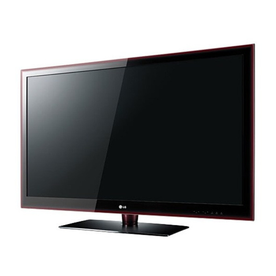
LED LCD TV
SERVICE MANUAL
CHASSIS : LD03E
MODEL: 42LE5500/550N
MODEL:
MODEL:
MODEL:
CAUTION
BEFORE SERVICING THE CHASSIS,
READ THE SAFETY PRECAUTIONS IN THIS MANUAL.
P/NO : MFL63263102 (1003-REV00)
42LE5800/5900
42LE5510/5810
42LE5910
/I
P
OK
MENU
INPUT
North/Latin America
Europe/Africa
Asia/Oceania
42LE5500/550N-ZA
42LE5800/5900-ZA
42LE5510/5810-ZB
42LE5910-ZB
Internal Use Only
http://aic.lgservice.com
http://eic.lgservice.com
http://biz.lgservice.com
Printed in Korea
Advertisement

Summarization of Contents
LED LCD TV Service Manual
Model and Chassis Information
Identifies the LD03E chassis and specific LG TV models covered.
Safety Warning
Alerts users to read safety precautions before servicing the unit.
Safety Precautions
Important Safety Notice
Highlights critical safety-related parts and the need for identical replacements.
General Servicing Guidance
Provides advice on using isolation transformers and handling fuses.
AC Leakage Current Checks
Details procedures for performing both cold and hot AC leakage current checks.
Specifications
Application Range and Test Requirements
Specifies application range and standard conditions for testing TV components.
Test Methods and Module Specs
Describes test methods and general specifications for the LCD module.
Module Specifications
Module Optical Specifications
Details optical parameters like viewing angle, luminance, and contrast ratio.
Component Video Input Standards
Lists resolutions, frequencies, and proposed standards for component video inputs.
Signal Input Specifications
RGB (PC) Input Standards
Specifies resolutions, frequencies, and pixel clocks for PC inputs.
HDMI Input Standards
Lists resolutions, frequencies, and pixel clocks for HDMI inputs in DTV and PC modes.
Adjustment Instructions
Adjustment Application and Guidelines
Specifies adjustment applicability and general servicing guidelines for LD03E chassis.
Automatic Adjustment (ADC) Procedure
Details automatic adjustment for ADC, including equipment and protocol.
MAC Address and Serial Communication
Covers MAC address editing and serial communication setup for adjustments.
Service Procedures
MAC Address Download and LAN Inspection
Covers downloading MAC addresses and performing LAN port inspection (PING test).
V-COM Adjustment Procedure
Explains the importance of Vcom adjustment for liquid crystal driving.
Advanced Service Functions
CI+ Key Download Method
Provides steps for downloading CI+ keys via RS-232C.
Model and Serial Number Download
Details methods for downloading model names and serial numbers using scan equipment or manual input.
Manual Adjustment Procedures
ADC (GP2) Adjustment Methods
Describes manual adjustment for ADC in 480i, 1080p, and 1920x1080 RGB modes.
EDID/DDC Download Process
Explains the process for downloading EDID data for Plug and Play functionality.
Adjustment Protocols and Calibration
RS-232C Adjustment Commands
Lists RS-232C commands used during auto-adjustment for white balance.
White Balance Adjustment Procedure
Details the objective and procedure for adjusting white balance across different color temperatures.
Adjustment Methods and Checks
Manual White Balance Adjustment
Explains manual methods for white balance adjustment.
EYE-Q and Local Dimming Checks
Covers procedures for checking the EYE-Q function and local dimming.
Configuration and Testing
Country and Tool Option Selection
Describes how to select country options and tool options for specific models.
Ship-out Mode, Pressure Checks, and Audio Specs
Details checks for ship-out mode, GND, pressure, and lists audio specifications.
Block Diagram
System Architecture Overview
Illustrates the overall system architecture and component connections.
Exploded View
Component Breakdown and Safety
Shows component breakdown with safety warnings for part replacement.
Memory and Model Configuration
Serial Flash, Boot Strap, and NAND Memory
Shows schematics for serial flash, boot strap, and NAND flash memory.
Model Option Settings
Illustrates model option settings related to memory and display types.
Signal Processing Blocks
Broad Band Studio and Input Circuits
Shows schematics for broad band studio, video, and audio input signal processing.
Memory and Core Circuits
DDR3 Memory Interface and URSA3 Core Power
Illustrates DDR3 memory interface and URSA3 core power supply circuits.
Interface Circuits
CI Interface and Component Input Schematics
Details schematics for CI interface and component input connections.
Audio and Video Inputs
Earphone and Rear CVBS Input Schematics
Illustrates schematics for earphone output and rear CVBS input.
Tuner and Power Supply
Tuner Circuit and Power Supply Schematics
Shows schematics for the tuner circuit and various power supply circuits.
USB Connectivity
USB2 Option Circuits
Details schematics for USB2 connectivity, including DVR ready.
Audio and AV Connections
SCART, Earphone Amp, and Audio Out Amp
Shows schematics for SCART, earphone amplifier, and audio output amplifier.
Bluetooth Module
Bluetooth for BCM Schematic
Shows the schematic for the Bluetooth module connected to the BCM.
CI Module Interface
CI Control Buffer and Power Enable
Details CI control buffer and power enable circuits for data transfer.
Mini LVDS Interface
Mini LVDS Interface Schematic
Shows the schematic for the Mini LVDS display interface.
LVDS Display Connectors
LVDS Connector Pinout Diagrams
Depicts the pinouts for LVDS connectors used for the display panel.
Power Management Circuits
Power Management IC Schematics
Illustrates various power management ICs and their associated circuits.
Micom and Configuration
Micom EEPROM and Model Options
Shows EEPROM schematic for micom and model option settings.
Input and Communication Interfaces
IR, Key, Wireless, RS232C, Ethernet
Covers IR/Key, wireless, RS232C, and Ethernet connection schematics.
Connectivity Ports and RGB Input
UI HDMI Ports and RGB PC Input
Shows schematics for HDMI ports and RGB PC input/audio.
Audio and Digital Outputs
SPDIF Out and RGB Audio In Schematics
Shows schematics for SPDIF output and RGB audio input.
Side AV Input
Side AV Input Schematic
Illustrates the schematic for the side AV input connections.
Wireless and Communication Control
Wireless Power, Control, and RS232C Status
Details wireless power, control circuits, and RS232C wireless status.
Audio Amplifier
Speaker Amplifier Schematics
Illustrates the schematic for the speaker amplifier circuits.
Memory and Core Power
DDR3 Memory Interface and URSA3 Core Power
Shows DDR3 memory interface and URSA3 core power supply circuits.
Core IC and Flash Memory
Serial Flash and URSA3 Main Processor
Details serial flash interface and URSA3 main processor schematic.
Display Driver Circuits
Level Shift, P-Gamma, HVDD, and Power Blocks
Illustrates display driver circuits including level shift, P-gamma, HVDD, and power blocks.
T-Con Power Options
T-Con Power Configurations for Panel Sizes
Details power option settings for different FHD panel sizes.


Need help?
Do you have a question about the 42LE5900 and is the answer not in the manual?
Questions and answers