Table of Contents
Advertisement
3211 Fruitland Ave
Los Angeles, CA 90058
SST2000 Series
Universal Speed Switch & Speed Transmitter
Installation and Operation Manual
Rev. C
P/N: 145F-11761
PCO – 00010383
(c) Copyright 2016, Barksdale, Inc.
All Rights Reserved
Published: Oct 20, 2016
中国授权代理商:信德迈科技(北京)有限公司
Phone:010-8428 395 Email: sales@cnmec.biz
网站: http://www.cnmec.biz/dynalco.htm
北京朝阳区望京SOHO-T1-C座2115室
Advertisement
Table of Contents

Related Manuals for Dynalco SST-2200A


Summary of Contents for Dynalco SST-2200A
- Page 1 3211 Fruitland Ave Los Angeles, CA 90058 SST2000 Series Universal Speed Switch & Speed Transmitter Installation and Operation Manual Rev. C P/N: 145F-11761 PCO – 00010383 (c) Copyright 2016, Barksdale, Inc. All Rights Reserved Published: Oct 20, 2016 中国授权代理商:信德迈科技(北京)有限公司 Phone:010-8428 395 Email: sales@cnmec.biz ...
- Page 2 Specifications and information herein are subject to change without notice. Dynalco reserves the right to make changes to the equipment described herein to improve function or design. Although the information contained in this manual has been carefully reviewed and is believed to be reliable, Dynalco Controls does not assume any liability for special, indirect, incidental, or consequential damages arising out of the application or use of the equipment described herein.
-
Page 3: Table Of Contents
Contents Chapter 1 Getting Started About your speed switch ........2 Models. -
Page 4: Getting Started
Chapter Getting Started... -
Page 5: About Your Speed Switch
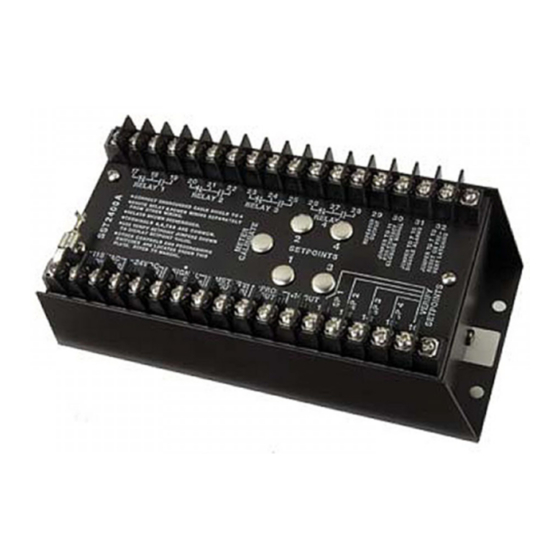
Chapter 1 About your speed switch WARNING When the SST-2000A/H Series Speed Switch/Transmitter is used as the primary overspeed shutdown device, it must be tested regularly. The SST-2000A/H series is a speed switch and signal transmitter that provides alarm set points for over- and underspeed control for sequential, startup, and shutdown switching for: engines machines... - Page 6 Getting Started Physical Dimensions Fig. 1-1 Top and side views of the SST-2000A/H. Dimensions in inches and (centimeters). Special explosion proof housings kits (complete with mounting hardware) are also available. See XP rated housings on page 6. 3.75 9.5 1.81 4.6 8.25 21 7.75 19.7 .25 0.64...
-
Page 7: Models
Chapter 1 Models No. Of Model 3rd Party Certification(s) Set Points A series – standard relays SST-2000A CSA: general certification LR 92270 ABS: type approval SST-2200A CE: 89/336/EEC, Light Industrial SST-2400A CE: 72/23/EEC, Low Voltage Directive H series – hermetically sealed relays SST-2000H CSA: Class I, Div. -
Page 8: Specifications
Getting Started Specifications Electrical Input Signal 0-20 kHz (standard) (field-adjustable) Frequency 0-0.1 Hz (special order) Range 0-80 Hz (special order) 0-50K Hz (special order) Waveforms Accepts pulsed, sinusoidal, square, TTL, or CMOS Input Signal 25 mVrms (typical factory setting) Sensitivity 5 mVrms to 100 mVrms (field-adjustable) 50 Vrms (maximum for standard units) 1.0 volt threshold (requires input signal desensitizing) - Page 9 Chapter 1 Relays Logic Field-programmable by switches for: overspeed/underspeed energize/de-energize latch/auto-reset SPST/DPDT (2 DPDT set points maximum) A Series 6.0 A @ 28 Vdc or 115 Vac (resistive) Contact Rating 2.0 A @ 220 Vac 1.0 A into 500 mH for up to 100,000 cycles SPDT* *For DPDT, Relays 1 &...
- Page 10 (field-configurable). NOTE: Not available with signal isolation transformer option. Pneumatic Trip Pulses relay 1 for 100 milliseconds Trips Dynalco SPV-200 Solenoid Pneumatic Valve on overspeed (optional) Underspeed Arms relay 2 as set point 2 is traversed on increasing speed.
-
Page 11: Installing The Sst-2000A/H
Chapter Installing the SST-2000A/H... -
Page 12: Mounting The Unit
Chapter 2 Mounting the unit The SST-2000A/H is installed using standard hand tools. It is generally mounted in a panel or enclosure using standard practices. About Electrical Connections Internal Commons, Isolation WARNING: AVOID DAMAGE WHEN DC-POWERED Install a current loop isolator between the 4–20mA output and the load if the load does not reference the same common as the SST-2000A/H. -
Page 13: Connecting Signal Inputs
Installing the SST-2000A/H Connecting Signal Inputs Connecting a PG-278 Pulser Connect signal source Common to terminal 6 on the SST-2000A/H. Connect signal HI to terminals on the SST-2000A/H. Fig. 2-2 Connecting a PG-278 Pulser to the SST-2000A/H. Terminals 11 and 30 on the SST-2000A/H are jumpered to create a one volt threshold. -
Page 14: Powering External Devices
Chapter Powering External Devices... -
Page 15: Powering An Spd-100, Spd-700, Or Other Frequency Instruments
Chapter 3 Powering an SPD-100, SPD-700, or other frequency instruments The SST-2000A/H has a repeater output that can be used to power external frequency instruments. A square wave (14-volt peak-to-peak, zero-based, positive-going) is brought out at terminals 29 and 4 (common) to drive self-powered digital tachometers such as the SPD-100, SPD-700, and MTH-103D, or to use as a conditioned high level signal source into counters or other instruments. - Page 16 Powering External Devices Confirm the meter is properly connected to the SST-2000A/H. Use a frequency generator (e.g. F-16) to apply full-scale frequency to terminal 5 (HI) & 6 (COM) on the SST-2000A/H. Maximum signal input is 50 Vrms for a standard unit. Adjust the potentiometer on the METER CALIBRATE...
-
Page 17: Powering Zero Velocity Pickups And Other Loads
Chapter 3 Powering Zero Velocity Pickups and Other Loads The regulated 14 Vdc supply brought out at terminals 11 (+) & 4 (–) has a capacity of 40 mA. This output can power zero velocity pickups (e.g. M928) and digital indicators like a DPM-105. Connect the M928 pickup as indicated in Fig. -
Page 18: Driving An Spv-200 Solenoid Pneumatic Valve
Powering External Devices Driving an SPV-200 Solenoid Pneumatic Valve WARNING: TO AVOID SPV-200 COIL DAMAGE Use a current limiting resistor in series with the dc power source and the transferring relay contacts. The SPV -200 coil has a resistance of 50 Ω and requires 6 Vdc to trip. Switching the Regulated 14 Vdc Supply The regulated 14 Vdc supply at terminals 11 (+) &... -
Page 19: Calibrating The Speed Switch
Chapter Calibrating the Speed Switch... -
Page 20: Locating The Programming Switch Instructions
Chapter 4 Locating the programming switch instructions Fig. 4-8 A full description of the programming switches and controls is located under the top plate of the SST-2000A/H. Use a no. 1 or no. 2 Phillips screwdriver to remove the top plate of the switch. -
Page 21: Changing The Full-Scale Input Frequency Range
Damage might result that could void the product warranty. Please contact the Dynalco Customer Service Department at (954) 739-4300 for guidance in arranging for a low input frequency range. Input frequency range greater than 20,000 Hz full-scale The full-scale frequency input range is usually set up at the factory when an SST-2000A/H is ordered. -
Page 22: Calibrating The Sst-2000A/H
Chapter 4 Calibrating the SST-2000A/H WARNING Calibrate the speed switch: • immediately after any contact change in Switch A • before adjusting set points or proportional output You must calibrate the SST-2000A/H if you have made a change in the full-scale frequency range (changed contacts to DIP switch A). - Page 23 Calibrating the Speed Switch Table 4-1 Table of Freq. Range Switch A ON Freq. Range full-scale frequency and (in kHz) Positions (in Hz) the corresponding switch 0.08 - 0.10 1, 8 80 - 100 “A” ON settings. 0.10 - 0.13 2, 8 100 - 130 0.13 - 0.17...
-
Page 24: Calibrating The 4-20 Ma Proportional Output
Chapter 4 Calibrating the 4-20 mA Proportional Output You must calibrate the speed switch if the standard proportional output of 4 to 20 mA is changed to : 0–5 Vdc using switch C1, or 0–10 Vdc using switch C2 To calibrate the new proportional output Attach a digital voltmeter to terminals 9 (–) &... -
Page 25: Programming Set Points And Relays
Calibrating the Speed Switch Programming Set Points and Relays Remove the top plate from the SST-2000A/H to reveal DIP switches B and C. Use DIP switches B and C to program relay set points to: energize (OFF) / de-energize (ON) on alarm non-latch (OFF) / latch (ON) on alarm actuate SPST (OFF) / DPDT (ON) trip on alarm change proportional voltage output... - Page 26 Chapter 4 Set points 3 & 4 and selecting DPDT trip WHEN ALL B THE EFFECT OF TURNING B SWITCHES ON SWITCHES ARE OFF Turn on B to... relays 3 and 4 are energized, LATCH set point 3 on alarm underspeed ACTUATE relay 4 simultaneously with relay 2, creating two Form non-latching...
-
Page 27: Adjusting Signal Sensitivity
Calibrating the Speed Switch Adjusting Signal Sensitivity Desensitizing Standard Inputs Signal sensitivity is factory set to 25 mVrms (about 35 mV peak or 70 mV peak-to-peak) and satisfies most applications. Fig. 4-12 signal sensitivity control is located under the A DIP switch. -
Page 28: Response Time
While other response times can be provided, field modification is not recommended since damage might result that could void the product warranty. Contact Dynalco if you need a different relay response time. Adjusting Individual Set Points Verify that the SST-2000A/H is calibrated to the correct full-scale frequency range (see page 22). - Page 29 Calibrating the Speed Switch Apply the calculated set point frequency to terminals 5 (HI) & 6 (COM). Apply operating power to the SST-2000A/H. See lid of your SST-2000A/H or spec sheet for power choices. Select the appropriate set point trim pot. Turn the pot: Counterclockwise to lower the set point value (reduce the speed at which the set point relay will trip ).
- Page 30 Chapter 4 an RPM indicator/tachometer operating from one of the proportional outputs of the SST-2000A/H: an independent meter mounted elsewhere on or near the engine. Wait for the RPM to stabilize. When RPM is stable, select the appropriate set point trim pot . Follow the procedure in Alternate Method 1: steps 1-10.
-
Page 31: Verifying Set Point Values
Calibrating the Speed Switch Verifying Set Point Values You can view and adjust the set point values without having to run the engine. NOTE: The SST-2000A/H (no set points) does not have set points. Jumper terminal 16 with the terminal that corresponds with the set point you want to view (for SST02200A/H and SST-2400A/H): The temporary Set point 1: jumper 16 to 12... -
Page 32: Adjusting Set Point Values
Chapter 4 Adjusting Set Point Values WARNING You can adjust set points while the engine or other device is operating. However, if you adjust a set point relay to a value lower than the current operating speed, the relay will trip. You will need a 0–1 mA meter for this procedure. - Page 33 Index calibrating, 19, 21 - 23, 25, 27, 29, model numbers, 4 commons, 10 contact closure, 27 output, 24 Class I, Div.2, Grp. D (H 4-20 mA , 24 series), 4 general certification (A series), current loop isolator, 10 PG-278 pulser, 11 pickups powering, 16 power...
Need help?
Do you have a question about the SST-2200A and is the answer not in the manual?
Questions and answers