
Related Manuals for Dynalco SWTD-1000


Summary of Contents for Dynalco SWTD-1000
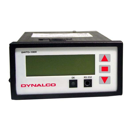
- Page 1 SWTD-1000 Speed Switch / Transmitter Operating Manual 3690 NW 53 Street • Fort Lauderdale, FL 33309 • Ph 954-739-4300 • Fax 954-486-4968 • www.dynalco.com...
-
Page 2: Table Of Contents
TABLE OF CONTENTS Safety Instructions Product Features Specifications General Inputs 3.2.1 Analog Sensor Connection (Sign) 3.2.2 Digital Sensor Connection (IQ) 3.2.3 Sensor Supply 3.2.4 Binary Input Outputs 3.3.1 Analog Output 3.3.2 Relay 3.3.3 Open Collector Output Data Communication 3.4.1 Serial Interface (RS 232) Environment 3.5.1 Climatic Conditions... -
Page 3: Safety Instructions
Instruments in a doubtful condition after electrical, climatic or mechanical overload must be immediately disconnected and returned to the manufacturer for repair. 2. Product Features The SWTD-1000 measures and monitor frequencies (speed proportional values) in the range 0 to 35,000 Hz. The following are available: •... -
Page 4: Specifications
Operating Instructions SWTD-1000 DYNALCO 3. Specifications 3.1 General SWTD-1000 Lowest measuring range 0 . . . 1.000 Hz Highest measuring range 0 . . . 35.00 kHz Minimum Measuring time Selectable values: 2 / 5 / 10 / 20 / 50 / 100 / 200 / 500ms (Fixtime) 1 / 2 / 5 Seconds. -
Page 5: Inputs
Operating Instructions SWTD-1000 DYNALCO 3.2 Inputs 3.2.1 Analog Sensor connection (Sign) Frequency range (-3dB) 0.01 Hz / 35 kHz Input impedance 30 K • Input voltage Max. 80V • Max. frequency against input voltage O.K. NOT O.K. Trigger: 500mVpp Trigger: 20mVeff 0.01... -
Page 6: Digital Sensor Connection (Iq)
Operating Instructions SWTD-1000 DYNALCO 3.2.2 Digital Sensor Connection (IQ) Frequency range (-3dB) 0.01 Hz / 35 kHz Input impedance 46 K Input voltage Max. ± 36V peek Minimum pulse width Min. pulse width 1.5 µs • Trigger level min.U = 1.6 V •... -
Page 7: Binary Input
Operating Instructions SWTD-1000 DYNALCO 3.2.4 Binary Input For external selection of Parameter set A or B. • Logic 1 = Parameter set A (Relay control A) • Logic 0 = Parameter set B (Relay control B) Levels Logic 1 = V > +3.5V Logic 0 = V <... -
Page 8: Relay
Operating Instructions SWTD-1000 DYNALCO 3.3.2 Relay Type Single Pole Double Throw Limit Hysteresis Programmable – 1 lower and 1 upper set point per limit. Functions 2 programmable parameter sets selectable via binary input • Reaction to Alarm, Sensor fault, Limit, always on or off. -
Page 9: Principle Of Operation
Principle of Operation 4.1 General The SWTD-1000 is controlled by a microprocessor. It works according to the period measurement principle whereby the input period is measured with subsequent computing of the reciprocal value corresponding to the frequency or speed. The relationship between frequency and speed is established with the Machine factor. -
Page 10: Machine Factor
Operating Instructions SWTD-1000 DYNALCO 4.2 Machine Factor The machine factor establishes the relationship between sensor frequency (Hz) and corresponding speed (RPM). Machine Factor = Frequency If the # gear teeth and RPM are known, use the following formula to calculate corresponding frequency:... -
Page 11: Installation
The SWTD-1000 may only be installed by trained and competent personnel. An undamaged SWTD-1000, valid configuration and suitable installation are required. Please note the Safety Instructions in Section 1. The power to the SWTD-1000 should be capable of being disconnected via a switch or other emergency means. -
Page 12: Terminals
Operating Instructions SWTD-1000 DYNALCO 6.2 Terminals SWTD-1000 Sh 0VS Ana. +Vout Dig. +Bin +PO -PO NC NO Com +AO -AO Gnd +24V Sensor connections Analog output : Screen – Sensor cable : current positive : Sensor Reference voltage - AO... -
Page 13: Hardware Configuration
Operating Instructions SWTD-1000 DYNALCO 7. Hardware Configuration 7.1 Analog Sensor Input (Sign) Jumper position J1: Sensor type J2: Adaptive trigger level range 2 wire sensors 28mV to 6.5V (>20mV (with 820Ohm Pull Up resistance) 3 wire and electromagnetic sensors 250mV to 6.5V (>500mVpp) -
Page 14: Configuration With Pc Software
Configuration with PC Software 8.1 Software Concept All settings are written via PC to the SWTD-1000 using the RS232 interface and the aid of the user friendly menu driven SWTD-1000 software. The parameter file may be stored, opened, printed and exchanged between the SWTD-1000 and a PC. -
Page 15: Parameter List And Ranges
Operating Instructions SWTD-1000 DYNALCO Parameter List and Ranges If you already have a configuration file you can open and view it using the SWTD-1000 Windows Software menu File Open You can also connect the SWTD-1000 to a PC (see section 8.2) and read back the parameters,... -
Page 16: Parameters
Sensor Type The type of sensor to be used is defined here. <Sensor active> is for monitoring sensors powered by SWTD-1000 including 2 wire sensors supplied via the internal pull up resistor. (Jumper J1). <Sensor passive> is for monitoring non powered sensors e.g. 2 wire VR (passive) sensors. -
Page 17: Analog Output (Configuration Analog Output)
0.0 seconds. 8.5.4 Limit (Configuration Limit) The SWTD-1000 series offers 2 independent limits Limit 1 and 2. Status Limits are selected here. If the limit is deactivated, the other values such as set points and mode have no further effect. -
Page 18: Relay Parameter And Selection Of Parameter Set
Operating Instructions SWTD-1000 DYNALCO 8.5.5 Relay Parameter and Selection of Parameter Set (Configuration Relay control) Parameter set A / B selection As standard parameter set B may be activated via the binary input <Binary input B1>. If parameter set B is to be deactivated, this setting should be none (always control A) Delay time when switching A <- B... -
Page 19: Operating Behavior
Operating Instructions SWTD-1000 DYNALCO 9. Operating Behavior Power On 9.1.1 Analog Output Following power on the output assumes the output range start value. Upon completion of the first measurement the output goes to the corresponding measured value. 9.1.2 Relay Output The parameter set determined by the configuration and binary input is valid from the start. -
Page 20: Signal Failure
Limts 1 and 2. 9.3.2 Parameter set A and B The SWTD-1000 has 2 parameter sets available that define the relay assignment. Parameter set A would normally be used. If another parameter set is needed, e.g. for test purposes, the binary input may be used to change to parameter set B. -
Page 21: Binary Input
If the current falls outside the permitted range then sensor fault is indicated. If the sensor is not powered by the SWTD-1000 then it may only be monitored for disconnection. If disconnected, sensor fauly is indicated. -
Page 22: Mechanical Construction / Housing
2.5 mm 2 - Cable or 1.5 mm2 flex AWG 24 – AWG 12 UL CSA Sealing to EN 60925 Housing IP 40 resp. IEC 925 Terminals IP 20 Dimensions 11. Accessories Interface cable PC – SWTD-1000, Part No. PC-T400 20//...
Need help?
Do you have a question about the SWTD-1000 and is the answer not in the manual?
Questions and answers