Advertisement
Quick Links
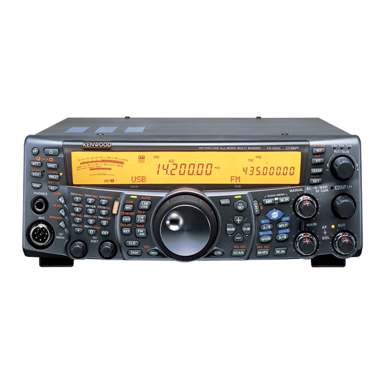
ALL MODE MULTI-BAND TRANSCEIVER
TS-2000/X
TS-B2000
SERVICE MANUAL
TS-2000/X
Phone jack (9P)
(E11-0438-05)
Key top (8 key)
(K29-5391-12)
Knob
(K29-5397-13) x 2
MIC connector (8P)
(E06-0858-15)
TS-B2000
Phone jack (9P)
(E11-0438-05)
MIC connector (8P)
(E06-0858-15)
SUPPLEMENT
Cabinet (Upper)
(A01-2176-11)
Knob ring (Main dial)
(K29-5395-04)
Key top (25 key)
(K29-5392-12)
Foot (Front)
Knob (Main dial)
(J02-0440-04)
(K21-1104-03)
Panel
(A62-0916-03)
© 2002-2 PRINTED IN JAPAN
B51-8622-00 ( N ) 791
Front glass
(B10-2608-12)
Knob (Outside)
(K29-5399-03) x 3
Key top (18 key)
(K29-5393-12)
Knob (Inside)
(K29-5398-03) x 3
Dressing plate
Cabinet (Upper)
(B03-3608-03)
(A01-2176-11)
Key top (4 key)
(K29-5394-22)
Knob (RIT, MULTI)
(K29-5396-03) x 2
Foot (Front)
(J02-0442-04) x 2
Foot (Front)
(J02-0442-04) x 2
Advertisement

Related Manuals for Kenwood TS-2000LE


Summarization of Contents
Description of Components
Final Unit (HF) Components
Lists and describes components of the Final Unit (HF) (X45-360X-XX) (A/2).
Parts List
TS-2000/X, TS-B2000 Parts
Provides a list of parts for the TS-2000/X and TS-B2000 models.
Adjustment Procedures
Display and PLL Checks
Checks display functionality and performs PLL circuit adjustments.
Receiver Section Adjustments
Procedures for adjusting receiver performance including BPF, RX trap, and sensitivity.
Transmitter Section Adjustments
Adjustments for transmitter power, gain, frequency response, and ALC.
PC Board Views and Schematic Diagrams
Filter Unit PC Board Views
Component and foil side views of the Filter Unit (X51-315X-XX).
Display Unit PC Board Views
Component and foil side views of the Display Unit (X54-3320-00).
Control Unit PC Board Views
Component and foil side views of the Control Unit (X53-391X-XX).
Overall Schematic Diagram
Schematic diagram showing the overall circuit connections of the transceiver.
Specifications
General Specifications
General specifications including frequency range, power, and dimensions.
Transmitter Specifications
Transmitter specifications covering frequency bands and output power.
Receiver Specifications
Receiver specifications including circuit type, sensitivity, and selectivity.
Selectivity Specifications
Details receiver selectivity characteristics for various modes and bands.
Need help?
Do you have a question about the TS-2000LE and is the answer not in the manual?
Questions and answers