Table of Contents
Advertisement
Quick Links
SPLIT-TYPE, HEAT PUMP AIR CONDITIONERS
SERVICE MANUAL
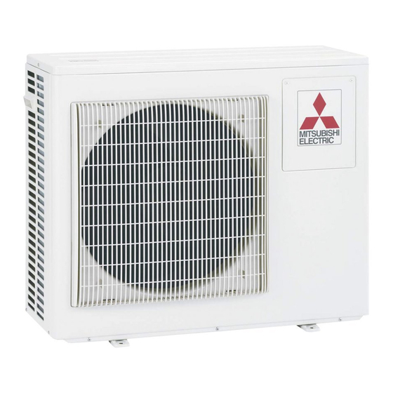
Outdoor unit
[Model Name]
PUHZ-ZRP35VKA
PUHZ-ZRP50VKA
PUHZ-ZRP60VHA
PUHZ-ZRP71VHA
PUHZ-ZRP100VKA
PUHZ-ZRP125VKA
PUHZ-ZRP140VKA
PUHZ-ZRP100YKA
PUHZ-ZRP125YKA
PUHZ-ZRP140YKA
[Service Ref.]
Refer to page 2.
PUHZ-ZRP35VKA
PUHZ-ZRP50VKA
R410A
CONTENTS
1. TECHNICAL CHANGES ································ 2
2. REFERENCE MANUAL ································· 3
3. SAFETY PRECAUTION ································· 3
4. FEATURES ····················································· 7
5. SPECIFICATIONS ·········································· 8
6. DATA ····························································· 10
7. OUTLINES AND DIMENSIONS ··················· 14
8. WIRING DIAGRAM ······································ 17
9. WIRING SPECIFICATIONS ·························· 22
10. REFRIGERANT SYSTEM DIAGRAM ············· 27
11. TROUBLESHOOTING ·································· 30
12. FUNCTION SETTING ··································· 96
13. MONITORING THE OPERATION DATA BY THE REMOTE CONTROLLER ··108
14. EASY MAINTENANCE FUNCTION ··········· 119
15. DISASSEMBLY PROCEDURE ··················· 126
PARTS CATALOG (OCB527)
July 2014
No. OCH527
REVISED EDITION-C
Revision:
• Added
PUHZ-ZRP35VKAR1,
PUHZ-ZRP35VKAR1-ER,
PUHZ-ZRP35VKAR1-ET,
PUHZ-ZRP50VKAR1,
PUHZ-ZRP50VKAR1-ER,
PUHZ-ZRP50VKAR1-ET,
PUHZ-ZRP60VHAR1,
PUHZ-ZRP60VHAR1-ER,
PUHZ-ZRP60VHAR1-ET,
PUHZ-ZRP71VHAR1,
PUHZ-ZRP71VHAR1-ER and
PUHZ-ZRP71VHAR1-ET in
REVISED EDITION-C.
• Some descriptions have been
modified.
• Please void OCH527
REVISED EDITION-B.
Note:
• This manual describes service
data of the outdoor units only.
Advertisement
Table of Contents

Summarization of Contents
TECHNICAL CHANGES
Service ref. have been changed as follows.
Details changes made to service references for various models, including added and modified descriptions.
REFERENCE MANUAL
Model Name Service Ref. Service Manual No.
Table listing model names, their corresponding service references, and service manual numbers.
SAFETY PRECAUTION
3-1. ALWAYS OBSERVE FOR SAFETY
General safety instruction emphasizing the disconnection of all supply circuits before access.
3-2. CAUTIONS RELATED TO NEW REFRIGERANT
Specific safety precautions for units utilizing R410A refrigerant, covering preparation and during service.
FEATURES
CHARGELESS SYSTEM
Describes the pre-charged refrigerant system for piping length at shipment, simplifying installation.
SPECIFICATIONS
OUTDOOR UNIT REFRIGERANT PIPING
Details specifications related to refrigerant piping for outdoor units, including pipe size and connection.
DATA
6-1. REFILLING REFRIGERANT CHARGE (R410A: kg) PUHZ-ZRP35-140
Table showing refrigerant charge amounts (kg) for various models based on piping length.
6-2. COMPRESSOR TECHNICAL DATA
Provides technical data for compressors, including model, winding resistance, and specifications.
OUTLINES AND DIMENSIONS
FOUNDATION BOLTS
Information regarding foundation bolts required for unit installation, including size and type.
PIPING-WIRING DIRECTION
Details on the direction for piping and wiring connections to the unit.
WIRING DIAGRAM
M-NET ADAPTER
Diagram and symbol list for the M-NET adapter connection and its components.
WIRING SPECIFICATIONS
9-1. FIELD ELECTRICAL WIRING (power wiring specifications)
Specifications for field electrical wiring, including circuit ratings, wire sizes, and breaker capacities.
9-2. SEPARATE INDOOR UNIT/ OUTDOOR UNIT POWER SUPPLIES
Illustrates connection patterns for separate power supplies between indoor and outdoor units.
9-3. INDOOR – OUTDOOR CONNECTING CABLE
Guidelines for selecting and connecting indoor-outdoor cables, including length and wire size specifications.
9-4. M-NET WIRING METHOD
Instructions for M-NET wiring, including points to note, earthing methods, and transmission wire types.
TROUBLESHOOTING
11-1. TROUBLESHOOTING
Guidance on diagnosing and taking corrective actions based on self-diagnosis check codes.
11-2. CHECK POINT UNDER TEST RUN
Pre-test run checks and procedures for testing operation via wired or wireless remote controllers.
11-3. HOW TO PROCEED "SELF-DIAGNOSIS"
Procedure for performing self-diagnosis using the remote controller, including error history and reset.
11-4. SELF-DIAGNOSIS ACTION TABLE
A table detailing check codes, abnormal points, detection methods, cases, and judgment/action.
HOW TO CHECK THE PARTS
Linear expansion valve
Details on linear expansion valve operation, including output pulse signals and connection diagrams.
EMERGENCY OPERATION
(1) When the check codes shown below are displayed on outdoor unit or microcomputer for wired remote controller or indoor unit has a failure, but no other problems are found, emergency operation will be available by setting the emergency operation switch (SWE) on indoor controller board to ON and short-circuiting the connector (CN31) on outdoor controller board.
Allows emergency operation when specific error codes are displayed or unit fails, by setting indoor SWE to ON and shorting CN31 on outdoor board.
TEST POINT DIAGRAM
Brief Check of POWER MODULE
Guidance on checking the power module (DIP-IPM and DIP-PFC) for short circuits.
FUNCTION OF SWITCHES, CONNECTORS AND JUMPERS
(1) Function of switches
Details the functions and action settings for various DIP switches and push switches.
(2) Function of connector
Explains functions of connectors, including emergency operation and special functions.
Special function
Describes modifications for low-level sound priority mode and on-demand control for energy saving.
FUNCTION SETTING
12-1. UNIT FUNCTION SETTING BY THE REMOTE CONTROLLER
Guide to setting various unit functions using the wired remote controller.
12-1-1. Selecting functions using the wired remote controller
Detailed procedure for selecting functions via PAR-30MAA/PAR-31MAA remote controller.
12-1-2. Selecting functions using the wired remote controller
Procedure for selecting functions using the PAR-21MAA remote controller, including flowcharts.
12-2. FUNCTION SELECTION OF REMOTE CONTROLLER
Overview of function buttons and menu structure for remote controller operation.
MONITORING THE OPERATION DATA BY THE REMOTE CONTROLLER
13-1. HOW TO "MONITOR THE OPERATION DATA"
Guide to monitoring operation data like thermistor temperatures and error history via remote controller.
13-1-1. PAR-30MAA/PAR-31MAA
Procedure for monitoring operation data using the PAR-30MAA/PAR-31MAA remote controller.
13-1-2. PAR-21MAA
Procedure for monitoring operation data using the PAR-21MAA remote controller.
13-2. Request code list
List of request codes for monitoring operation data, including descriptions and units.
EASY MAINTENANCE FUNCTION
14-1. SMOOTH MAINTENANCE
Procedure for smooth maintenance to check operation data like temperatures and compressor current.
14-2. INITIAL SETTINGS FOR REFRIGERANT LEAKAGE DETECTION FUNCTION
Steps for initial learning and settings required to enable refrigerant leakage detection function.
DISASSEMBLY PROCEDURE
1. Removing the service panel and top panel
Step-by-step guide to remove the service and top panels of the outdoor unit.
2. Removing the fan motor (MF1)
Procedure to remove the fan motor, including disconnecting connectors and unscrewing mounting screws.
12. Removing the compressor (MC)
Detailed steps to remove the compressor, including disconnecting pipes and fixing nuts.
13. Removing the power receiver
Steps to remove the power receiver, including disconnecting pipes and securing receiver legs.


Need help?
Do you have a question about the Mr. Slim PUHZ-ZRP50VKA and is the answer not in the manual?
Questions and answers