Advertisement
Quick Links
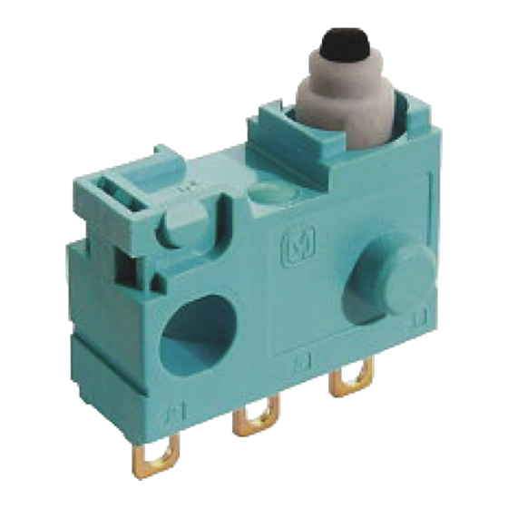
For detection: Seal Type Switches
Turquoise Stroke Switches
Long Stroke and Sliding Contact Construction Sealed Switches
13.3
10.1
ORDERING INFORMATION (PART NO.)
Size of mounting hole
Terminal
2: Wire leads right side type
0: Mounting hole 3 mm
standard type
(SPST-NC and SPST-NO only)
1: Mounting hole 3 mm
without boss type
4: Right side pin type
4: Solder
(solder terminal only)
5: Left side pin type
(solder terminal only)
6: Right 2 boss type
(solder terminal only)
7: Left 2 boss type
7: P/C board right angle
(solder terminal only)
Note) Not every combination is available. Please refer to the following table, "PRODUCT TYPES" .
2021.10
industrial.panasonic.com/ac/e/
5.4
(Unit : mm)
ASQ1
3: Wire leads left side type
(SPST-NC and SPST-NO only)
5: P/C board
6: Wire leads
terminal
bottom type
terminal
8: P/C board left angle
terminal
terminal
FEATURES
Long stroke: over travel (OT) is 2.2 mm or more on
the NO side and 2.5 mm or more on the NC side (for
pin plunger type)
Constructed so that the contact force does not
depend on the operation stroke.
High contact reliability to support low level switching
loads.
Highly effective sealing for resistance against
adverse environments
Silent operation with sliding contact
TYPICAL APPLICATIONS
Automobiles (detection of door opening and closing
and shift lever position, etc.)
Electric tool and household appliances (vacuum
cleaners, air conditioners, washing machines, etc.
Contact form
1: SPDT
2: SPST-NC
(wire lead type only)
COM
N.O. N.C.
COM
ー 1 ー
Panasonic Corporation 2021
Actuator
3: SPST-NO
0: Pin plunger
(wire lead type only)
7: Leaf lever
8: Simulated
leaf lever
N.C.
COM
N.O.
AECTB6E 202110
Advertisement

Related Manuals for Panasonic ASQ10410


Summarization of Contents
ORDERING INFORMATION
Size of mounting hole
Defines the mounting hole size options for the switch body.
Terminal type
Specifies the type of electrical terminal connection for the switch.
Contact form
Indicates the electrical contact configuration (e.g., SPDT, SPST-NC).
Actuator type
Describes the type of actuator mechanism used for switch operation.
SWITCH TYPES
Terminal type
Categorizes switches based on their terminal connection configurations.
Wire leads bottom type
Specifies switches with wire leads exiting from the bottom of the unit.
Wire leads side type
Details switches featuring wire leads exiting from the side of the unit.
RATING AND CONDITIONS
Contact rating
Electrical rating specifying voltage and current limits for the switch.
Operation environment and conditions
Specifies acceptable operating and storage parameters like temperature and speed.
Electrical characteristics
Details dielectric strength, insulation resistance, and contact resistance.
Protection grade
Specifies the switch's resistance to dust and water ingress based on IP codes.
OPERATING CHARACTERISTICS
Operating Force (OF) Max.
Maximum force required to operate the switch's actuator.
Total Travel Position (TTP)
The final position of the actuator after the full stroke of operation.
Free Position (FP) Max.
The position of the actuator when no force is applied.
Operating Position (OP)
The point at which the switch contacts change state during operation.
Release Position (RP)
The point at which the switch contacts return to their default state.
Over travel (OT)
The distance the actuator moves past the operating position before stopping.
EXTERNAL DIMENSIONS
Pin plunger type
Detailed physical measurements for the pin plunger actuator type.
Leaf lever type
Detailed physical measurements for the leaf lever actuator type.
Simulated leaf lever type
Detailed physical measurements for the simulated leaf lever actuator type.
P/C board terminal type
Physical dimensions for switches with P/C board terminal connections.
Right side pin type
Physical dimensions for switches with right side pin terminals.
Left side pin type
Physical dimensions for switches with left side pin terminals.
Right 2 boss type
Physical dimensions for switches with right 2 boss type terminals.
Left 2 boss type
Physical dimensions for switches with left 2 boss type terminals.
Angle terminal type (Right)
Physical dimensions for switches with right angle terminals.
Angle terminal type (Left)
Physical dimensions for switches with left angle terminals.
Wire leads bottom type
Physical dimensions for switches with wire leads from the bottom.
Wire leads right side type
Physical dimensions for switches with wire leads from the right side.
Wire leads left side type
Physical dimensions for switches with wire leads from the left side.
USAGE GUIDELINES
Soldering conditions
Precautions for applying heat to terminals during soldering to prevent damage.
Mounting instructions
Guidance on securing the switch body and avoiding undue force.
Circuit precautions
Recommendations for preventing malfunctions due to switch bounce and inductive loads.
Oil-proof and chemical-proof characteristics
Information on how oil and chemicals affect the switch's rubber cap and sealing.
Environmental considerations
Guidelines for operating the switch within specified temperature and humidity ranges.
OTHER CONSIDERATIONS
Handling precautions
Warnings against breaking the rubber cap and potential water seepage.
Environmental restrictions
Avoidance of silicon-based substances and flammable/explosive gases.
Operational limits
Avoid exceeding total travel position and precautions for high-speed operation.
NOTES FOR SPECIFIC SWITCH TYPES
Fastening of the switch body
Guidelines for securing the switch body with screws and appropriate torque.
Soldering operations
Recommendations for manual soldering and terminal post-soldering stability.
Cautions regarding use
Advice on inductive loads, phase synchronization, and lever type limitations.
Protection from dust, water and corrosive gas
Details on sealed construction and avoiding silicon gas sources.
TESTING AND REFERENCE
Dust protection test
Details of the test procedure for dust ingress protection.
Waterproof test
Details of the immersion test for water-resistance rating.
Hydrogen sulfide exposure test
Test conditions and results for exposure to hydrogen sulfide.
Oil-proof and chemical-proof characteristics
Effect of oil and chemicals on elastomer swelling and solvent restrictions.
PROTECTION LEVEL DEFINITIONS
IEC IP Codes
Explanation of IP characteristic codes for dust and water protection levels.
1st Characteristics number
Defines protection levels against solid matter (dust) based on IEC standards.
2nd Characteristics number
Defines protection levels against liquid matter (water) based on IEC standards.
Need help?
Do you have a question about the ASQ10410 and is the answer not in the manual?
Questions and answers