Table of Contents
Advertisement
FoxGate S6200 Series Installation Guide
Content
CHAPTER 1 INTRODUCTION....................................................... 1
1.1.1 Features and Benefits ............................................................................. 1
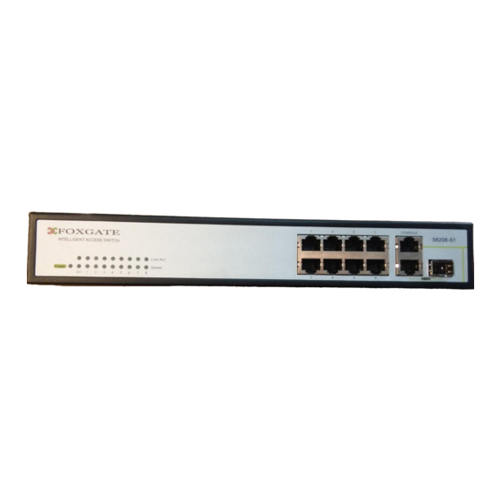
1.3.1 Front Panel ............................................................................................... 3
1.3.2 Back Panel................................................................................................ 4
1.3.3 Status LEDs.............................................................................................. 4
1.3.4 Front Panel Port Description .................................................................. 6
CHAPTER 2 HARDWARE INSTALLATION .................................. 1
2.1.1 Environmental Requirements ................................................................. 1
2.1.2 Installation Notice .................................................................................... 4
2.1.3 Security Warnings ................................................................................... 5
2.2.1 Verify the Package Contents................................................................... 5
2.2.2 Required Tools and Materials ................................................................. 6
2.3.1 Installing the Switch ................................................................................ 6
2.3.2 Connecting Console ................................................................................ 7
2.3.3 SFP Transceiver Installation ................................................................... 7
2.3.4 Copper Cable/Fiber Cable Connection .................................................. 8
2.3.5 Power Supply Connection ...................................................................... 9
Content
........................................................................................1
.........................................................................2
.....................................................................3
................................................................................1
......................................................................5
.................................................................................6
1
Advertisement
Table of Contents

Related Manuals for FoxGate S6208-S1


Summary of Contents for FoxGate S6208-S1
-
Page 1: Table Of Contents
FoxGate S6200 Series Installation Guide Content Content CHAPTER 1 INTRODUCTION............1 1.1 P ..................1 RODUCT RIEF 1.1.1 Features and Benefits ................1 1.2 P .................2 HYSICAL PECIFICATIONS 1.3 D ..............3 ESCRIPTION OF ARDWARE 1.3.1 Front Panel ....................3 1.3.2 Back Panel....................4 1.3.3 Status LEDs.................... -
Page 2: Chapter 1 Introduction
Chapter 1 Product Brief FoxGate S6224-S4: FoxGate S6224-S2 Foxgate S6208-S1 Features and Benefits 1.1.1 Various Interfaces FoxGate S6200 series switches provide multiple fixed 10/100Base-t ports and SFP COMBO ports. Networking Protocols FoxGate S6200 series switches support 802.1d/w/s, 802.1Q, 802.1p, 802.3ad,... -
Page 3: Physical Specifications
3D-SMP Ready FoxGate S6200 series are up to the mustard of Self-defending security region management strategy. It is supported interaction with some security system such as firewall,IDS,etc. It can defense the virus and aggress effectively from the extranet and internet. -
Page 4: Description Of Hardware
Description of Hardware Front Panel 1.3.1 FoxGate S6208-S1 series has 8 10/100Base-T ports, 1 Combo ports (1 RJ-45 and 1 SFP port), 1 Console port and 19 LEDs. The front panel of FoxGate S6208-S1 is shown below: FoxGate S6224-S2 series has 24 10/100Base-T ports, 2 Combo ports (1 RJ-45 and 1 SFP port), 1 Console port and 19 LEDs. -
Page 5: Back Panel
Back Panel 1.3.2 、FoxGate S6224-S2/S4 and Foxgate S6208-S1 have a 220V AC power receptacle. Status LEDs 1.3.3 FoxGate S6224-S4 series include port indicator and system status indicator, as shown in below and described in the following table. 1.3.3.1 Port Indicator Description... - Page 6 FoxGate S6200 Series Installation Guide Chapter 1 Introduction Table 1-1 FoxGate S6200 series port indications description Panel Symbol Status Description On (Green) The port is linked successfully Port1- The port is linked successfully, and 24(Link/Act) Flash(Green) receive/send data The port is not link...
-
Page 7: Front Panel Port Description
FoxGate S6200 Series Installation Guide Chapter 1 Introduction Front Panel Port Description 1.3.4 Each port description are shown below: Table 1-3 FoxGate S6224-S4 port description Interface mode Spec • RJ-45 port 10/100Mbps auto negotiation • MDI/MDI-X cable mode auto negotiation •... -
Page 8: Chapter 2 Hardware Installation
2.1.1.1 Dust and Particles Dust is harmful to the safe operation of FoxGate S6200 series. Dust can lead to electrostatic adherence, especially likely under low relative humidity, causing poor contact of metal connectors or contacts. Electrostatic adherence will result in not only reduced product lifespan, but also increased chance of communication failures. - Page 9 FoxGate S6200 Series Installation Guide Chapter 2 Hardware Installation In addition, salt, acid and sulfide in the air are also harmful to the switch. Such harmful gases will aggravate metal corrosion and the aging of some parts. The site should avoid harmful gases, such as SO...
- Page 10 FoxGate S6200 Series Installation Guide Chapter 2 Hardware Installation continued operation and an annual cumulative total of less than 15 days. Formidable operation conditions refers to the ambient temperature and relative humidity value that may occur during an air-conditioning system failure, and normal operation conditions should be recovered within 5 hours.
-
Page 11: Installation Notice
Caution! If a standard 19’’ rack is not available, the FoxGate S6224-S2/S4 series can be placed on a clean level desktop, leave a clearance of 10mm around the switch for ventilation, and do not place anything on top of the switch. -
Page 12: Security Warnings
FoxGate S6200 Series Installation Guide Chapter 2 Hardware Installation Security Warnings 2.1.3 When using SFP transceiver, do not stare directly at the fiber bore when the switch is in operation. Otherwise the laser may hurt your eyes. Do not attempt to conduct the operations which can damage the switch or which can cause physical injury. -
Page 13: Required Tools And Materials
Installing the Switch 2.3.1 Please mount the switch as below: 1. Attach the 2 brackets on the FoxGate S6224-S2/S4 series with screws provided in the accessory kit. Fig 2-1 Fasten the Brackets to the Switch 2. Put the bracket-mounted switch smoothly into a standard 19’’ rack. Fasten the FoxGate S6224-S2/S4 series to the rack with the screws provided. -
Page 14: Connecting Console
Do not block the blowholes on the switch to ensure the proper operation of the switch. Connecting Console 2.3.2 FoxGate S6224-S2/S4 series provide a DB9 serial console port and FoxGate S6208- S1 RJ-45 console port Fig 2-3 Connecting Console to FoxGate S6200 series The connection procedure is listed below: Find the console cable provided in the accessory kit. -
Page 15: Copper Cable/Fiber Cable Connection
FoxGate S6200 Series Installation Guide Chapter 2 Hardware Installation Caution! Do not stare directly at the 2 fiber bore in the SFP transceiver when the switch is in operation, otherwise the laser may hurt your eyes. Copper Cable/Fiber Cable Connection 2.3.4... -
Page 16: Power Supply Connection
Chapter 2 Hardware Installation Power Supply Connection 2.3.5 FoxGate S6200 series use the power is 220VAC. Please read the power input specification for the detailed information. AC Power supply connection procedure is described as below: Fig 2-4 Attaching power cable to FoxGate S6200 series 1.
Need help?
Do you have a question about the S6208-S1 and is the answer not in the manual?
Questions and answers