Table of Contents
Advertisement
Quick Links
Advertisement
Table of Contents

Related Manuals for Haloview CA115


Summary of Contents for Haloview CA115
-
Page 2: Table Of Contents
Contents Product Overview 2. Pair Button 3. Installation CA112 Camera CA115 Camera CA116 Camera 4. CA116 Installation CA116 Installation without drilling holes 5. Connecting the Camera 6. Connecting the Traffic Light 7. Camera Specification... -
Page 3: Product Overview
PRODUCT OVERVIEW PAIR BUTTON INSTALLATION CA112 Camera Ca112 Left Side/Right Side Camera Package Contents: 1. Manual 2. 3dBi 2.4G Antennas x 2PCS 3. 410 self-tapping self-drilling screws M4.2*19mm (10PCS) 4. Terminal Cap x 8PCS Fig.1 Fig.2 Figure1/Figure2 Remove Marker Light From vehicle... - Page 4 Fig.3 Fig.4 Figure3: Unscrew the LED Marker Light Figure4: Remove the marker light and pull out the cables Fig.5 Fig.6 Figure5: Cutting the cables by a plier Figure6:Stripping the cables to expose the conductive core Fig.7 Fig.8 Fig.9 Fig.10 Figure7/Figure8/Figure9: Ensure correct polarity when wiring the cables. Red + Black -...
- Page 5 Fig.11 Fig.12 Figure10/Figure11: Wire connections and terminals must be sealed and waterproof. Fig.13 Fig.14 Fig.15 Fig.16 Figure12/Figure13/Figure14/Figure15: Clamp the terminal tightly to make sure they are sealed and waterproof. Figure16:Put the wires and terminals into hole and align the camera to screw holes.
-
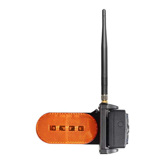
Page 6: Ca115 Camera
Fig.19 Fig.20 Figure17/Figure18: Remove the LED cover by straight screwdriver Figure19: Secure the LED base on the vehicle wall using the four self-tapping screws. Fig.21 Figure20/Figure21: Replace the LED cover. Installation done. CA115 Camera 1. Manual 2. 3dBi 2.4G Antenna x 1PC 3. - Page 7 Fig.3 Fig.4 Figure1/Figure2/Figure3: Remove Rear Light From vehicle by straight screwdriver Fig.5 Fig.6 Figure6: Remove the rear light and pull out the cables Fig.7 Fig.8 Figure7/Figure8: Cutting the cables by a plier and stripping the cables to expose the conductive core Fig.9 Fig.10 Figure9/Figure10/Figure11: Secure the rear light camera base on the...
- Page 8 Fig.11 Fig.12 Figure12/Figure13: Secure the base with four provided screws. Fig.13 Fig.14 Figure6: Remove the rear light and pull out the wires Fig.15 Fig.16 Figure15/Figure16: Wire connections and terminals must be sealed and waterproof. Fig.17 Fig.18 Figure17/Figure18/Figure19: Clamp the terminal tightly to make sure they are sealed and waterproof.
- Page 9 Fig.19 Fig.20 Figure17/Figure18/Figure19: Clamp the terminal tightly to make sure they are sealed and waterproof. Fig.21 Fig.22 Figure20/Figure21: Put the wires and terminals into hole and fasten the rear light camera into base. Fig.23 Fig.24 Figure22/23: Remove the cover of rear light camera and secure the base with four provided screws.
-
Page 10: Ca116 Camera
CA116 Camera CA116 Rear Camera Package Contents: 1. Manual 2. 3dBi 2.4G Antenna x 1PC 3. 3.5mm to DC power cable x 1PC 4. DC power cable to 2P wires x 1PC 5. PB Stainless steel flat tail screws M3*10mm (5PCS) 6. - Page 11 Fig.5 Fig.6 Figure5/Figure6/Figure7: Fix the gasket and bracket to the vehicle Figure8, make sure the power cable is not wrapped or extruded. Fig.7 Fig.8 Fig.9 Fig.10 Figure8/Figure9/Figure10: Make sure the sealing lip around the edge of the gasket is seated over the edge of bracket before fully tightening the provided screws.
- Page 12 Fig.13 Fig.14 Figure11/Figure12/Figure13/Figure14: Pull out the power cable. Connect the 3.5mm to DC power cable. Connect the power cable to camera cable. Fig.15 Fig.16 Fig.17 Fig.18 Figure17/Figure18: Secure the camera on bracket housing with provided screws. Make sure the connections and the camera antenna are secured tightly.
-
Page 13: Ca116 Installation Without Drilling Holes
CA116 Installation without drilling holes Fig.1 Fig.2 Figure1/Figure2: Remove LED From vehicle by straight screwdriver Fig.3 Fig.4 Figure1/Figure2: Remove LED From vehicle by straight screwdriver Fig.5 Fig.6 Figure5/Figure6: Cutting the cables by a plier and stripping the cables to expose the conductive core -11-... - Page 14 Fig.7 Fig.8 Figure7/Figure8: Ensure correct polarity when wiring the cables. Red + Black - Fig.9 Fig.10 Figure9/Figure10: Clamp the terminal tightly to make sure they are sealed and waterproof. Fig.11 Fig.12 Fig.13 Figure11/Figure12/Figure13: Wire connections and terminals must be sealed securely and waterproof. -12-...
- Page 15 Fig.14 Fig.15 Fig.16 Fig.17 Figure14/Figure15/Figure16: Take out the base from bracket housing. Fig.18 Fig.19 Figure17/Figure18: Insert magnet into base Fig.20 Fig.21 -13-...
- Page 16 Fig.22 Fig.23 Figure19/Figure20/Figure21/Figure22: Lock the magnet with bracket by torx screw. Fig.24 Fig.25 Figure23/Figure24: Connect the power cable to the camera cable. Bend the cable and tuck it into bracket housing. Fig.26 Fig.27 Figure25/Figure26: Remove the hole shield on the bracket base. Pull cables through the hole.
- Page 17 Fig.30 Fig.31 Fig.32 Fig.33 Fig.34 Fig.35 Fig.36 Figure31/Figure32/Figure33/Figure34/Figure35/Figure36: Remove the protector of metal plate and 3M tape. -15-...
- Page 18 Fig.37 Fig.38 Figure37/Figure38: Stick the metal plate on flat surface of vehicle Fig.39 Fig.40 Fig.41 Fig.42 Figure39/Figure40/Figure41: Adsorb the camera on metal plate Figure42: Put the LED back and secure it with screws. Fig.43 Fig.44 Figure43/Figure44: Replace the cover of LED. Installation done. -16-...
-
Page 19: Connecting The Camera
Ensure correct polarity when wiring the cables. RED + BLACK -. Wire connections and terminals must be sealed and waterproof. The haloview camera system can be connect to an electrical power source via a 7 way connector Wiring to running lights: the camera will active when the running lights are switched on. -
Page 20: Connecting The Traffic Light
Connecting the Traffic Light Route the power cable to the vehicle’s 12/24V running light. The cable must not interfere with the safe operation of the vehicle. Care and Cleaning Though your monitor requires little care,you will still need to maintain its condition and performance by following the guidelines below. -
Page 21: Camera Specification
CAMERA SPECIFICATION Image Device 1/4" CMOS 25 f/s 30 f/s TV System Effective Pixels 1280×720 pixels Pixel Size 3.0um×3.0um Video Output 8bits YUV Scanning System Progressive Scanning Sync. System Internal 0.45 Gamma Consumption Auto White Balance Auto Auto Electronic Rolling Shutter Electronic Shutter Operation Frequency 2412-2467MHz...
Need help?
Do you have a question about the CA115 and is the answer not in the manual?
Questions and answers