
Related Manuals for Metallkraft ULMS 500


Summary of Contents for Metallkraft ULMS 500
- Page 1 Instruction Manual Automatic light alloy metal cutting saw ULMS 420 ULMS 500 ULMS 420...
-
Page 2: Table Of Contents
1.1 Copyright ............3 1.2 Customer service..........3 Automatic light alloy metal-cutting saw Item number 1.3 Disclaimer ............3 2 Safety ............3 ULMS 420 3627420 2.1 Legend of symbols..........3 ULMS 500 3627500 2.2 Operator responsibility........4 2.3 Qualification of the staff ........4 2.4 Personal protective equipment ...... -
Page 3: Introduction
You have made an excellent choice in purchasing a All data in this operation manual has been compiled on METALLKRAFT Automatic light alloy metal-cutting saw. the basis of the state-of-the-art, valid standards and gui- delines as well as our many years of expertise and expe- Carefully read the operating instructions prior to rience. -
Page 4: Operator Responsibility
Safety - Operators shall obtain information about valid oc- cupational safety regulations and determine addi- tional hazards as part of a risk assessment which result from the specific operating conditions at the DANGER! machine's installation location. Said risk assess- This combination of symbol and signal word indicates ment shall be reflected in operating instructions for an imminently dangerous situation that will result in machine operation. -
Page 5: Personal Protective Equipment
Safety These operating instructions specify the following per- sonal qualifications for the different tasks: Use suitable Protective gloves Operating staff: Protective gloves protect the hands from compo- nents with sharp objects as well as friction, abrasion, Operating staff has undergone an induction by the oper- and deep-cut injuries. -
Page 6: Safety Labels On The Machine
Intended Use - The installation site should comply with the standards The safety symbols attached to the machine must not be for electrical wiring and equipment as well as the rules removed. Damaged safety symbols must be re-placed set by the authorized institutions. immediately. -
Page 7: Residual Risks
Technical Data 3.2 Residual risks Technical Data ULMS 420 ULMS 500 Even if all safety regulations are observed and the de- Engine speed 2900 2347 vice is used correctly, there are still residual risks, which [min¯¹] are listed below: Drive power - Risk of injury to the upper limbs (e.g. - Page 8 Technical Data Cutting diagram and dimensions of the model ULMS Cutting diagram and dimensions of the model ULMS Fig. 4: Cutting chart ULMS 500 Fig. 2: Cutting chart ULMS 420 1134 1357 Fig. 5: Dimensions of ULMS 500 Fig. 3: Dimensions Model ULMS 420...
-
Page 9: Type Plate
The Automatic light alloy metal-cutting saw may only be loaded and unloaded by qualified specialist personnel. WARNING! Fig. 6: Type plate ULMS 420 Danger to life due to falling of the Transport, Packaging, Storage load! Falling loads can cause serious injury or even death. -
Page 10: Packaging
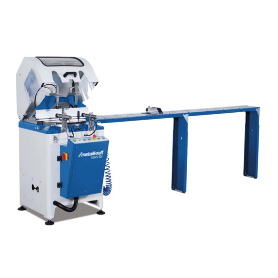
During storage, all electrical drives and control compo- nents should be covered with a plastic film. All bare me- tal surfaces are to be provided with a suitable rust pro- tection. Fig. 7: Device description ULMS 420 and ULMS 500 ULMS-Series | Version 2.04... -
Page 11: Scope Of Delivery
The machine is factory-installed and delivered to the cu- stomer. To ensure good functionality and a long service life of the Fig. 8: Installation of the feet on model ULMS 420 Automatic light alloy metal-cutting saw, the installation site should fulfil the following criteria:... -
Page 12: Mounting The Second Suction Nozzle
- Do not leave the unit unattended when it is connected to the mains. 7.4 Installation of the cutting tool Replacing the saw blade on the ULMS 420 and ULMS 500 models Fig. 10: Assembly of the suction connection part 1 Step 4: Remove the bracing (Pos.3, Fig.11) -
Page 13: Replacing The Tensioning Belt On The Ulms 500
Assembly and Installation Step 8: Hold the saw blade by hand and tighten the allen screw M10x20 with the Allen key. DANGER! Always unplug the power cord before changing the When you have completed the above steps, the saw is saw blade. -
Page 14: Connection Of The Clamping Device
Operation 7.6 Connection of the clamping device DANGER! Risk of injury! Model ULMS 420 und ULMS 500 When working on the Automatic light alloy metal-cut- Pneumatic hold-down clamps automatically clamp the ting saw workpiece as soon as the protective cover is closed. It is - is to wear tight-fitting clothing. -
Page 15: Application Of The Machine
Operation 8.2 Application of the machine Control panel model ULMS 420 and ULMS 500 Model ULMS 420 and ULMS 500 Step 1: Move the main switch from position (0) to posi- tion (1) (fig.15). Step 2: Set the pressure to 6 bar. -
Page 16: Settings
Step 8: Turn off the engine by pressing the MOTOR STOP button after the cutting process is over. Adjusting the cutting angle for model ULMS 420 and Step 9: Turn off the MAIN switch when you stop working ULMS 500 (Fig.18) with the machine. -
Page 17: Care, Maintenance And Repairs
Care, Maintenance and Repairs Check direction of motor rotation NOTE! DANGER! After cleaning, maintenance and repairs, make sure that all panels and protective guards are once again The three phases must be connected in such a way correctly in place on the machine and that there are that the saw blade moves according to the cutting no tools on the inside or outside of the machine. -
Page 18: Cleaning And Lubrication Of The Machine
Care, Maintenance and Repairs Treat bare metallic work surfaces with anti-rust spray. NOTE! 10.1.1 Fill in hydraulic oil The machine is not covered by the warranty in case of the following circumstances: Oil tank capacity: 1 liter - Defects and defects due to used conditioner oil, - Faults and defects due to the full and not dischar- Oil: Shell Tellur C19, BP Energol HLP 10, Petrol Ofisi Spin- ged water tank... -
Page 19: Troubleshooting
Troubleshooting 11 Troubleshooting NOTE! If you can not solve the problems with your machine yourself, then please contact your nearest METALL- KRAFT dealer. Please write down the following infor- mation from the machine or the operating instructions in advance to help you with your problem in the best possible way. -
Page 20: Disposal, Recycling Of Old Equipment
(Applicable in the countries of the European Union and The sawblade for the underfloor light metal circular saw other European countries with a separate collection sy- ULMS 420 must be ordered. The sawblade has the stem for these appliances). number 10 in the spare parts drawing 2. -
Page 21: Spare Parts Drawings
The following drawings are intended to identify the required spare parts in the event of service. If applicable, submit a copy of the parts drawing including the highlighted components to your authorised retailer. Spare parts drawing 1 - ULMS 420 Fig. 23: Spare parts drawing 1 - ULMS 420 ULMS-Series | Version 2.04... - Page 22 Spare parts Spare parts drawing 2 - ULMS 420 Fig. 24: Spare parts drawing 2 - ULMS 420 ULMS-Series | Version 2.04...
- Page 23 Spare parts Spare parts drawing 3 - ULMS 420 Fig. 25: Spare parts drawing 3 - ULMS 420 ULMS-Series | Version 2.04...
- Page 24 Spare parts Spare parts drawing 4 - ULMS 420 Fig. 26: Spare parts drawing 4 - ULMS 420 ULMS-Series | Version 2.04...
- Page 25 Spare parts Spare parts drawing 5 - ULMS 420 Fig. 27: Spare parts drawing 5 - ULMS 420 Spare parts drawing 6 - ULMS 420 Fig. 28: Spare parts drawing 6 - ULMS 420 ULMS-Series | Version 2.04...
- Page 26 Spare parts Spare parts drawing 7 - ULMS 420 Fig. 29: Spare parts drawing 7 - ULMS 420 ULMS-Series | Version 2.04...
- Page 27 Spare parts Spare parts drawings ULMS 500 Spare parts drawing 1 - ULMS 500 Fig. 30: Spare parts drawing 1 - ULMS 500 ULMS-Series | Version 2.04...
- Page 28 Spare parts Spare parts drawing 2 - ULMS 500 Fig. 31: Spare parts drawing 2 - ULMS 500 ULMS-Series | Version 2.04...
- Page 29 Spare parts Spare parts drawing 3 - ULMS 500 Fig. 32: Spare parts drawing 3 - ULMS 500 ULMS-Series | Version 2.04...
- Page 30 Spare parts Spare parts drawing 4 - ULMS 500 Fig. 33: Spare parts drawing 4 - ULMS 500 Spare parts drawing 5 - ULMS 500 Fig. 34: Spare parts drawing 5 - ULMS 500 ULMS-Series | Version 2.04...
- Page 31 Spare parts Spare parts drawing 6 - ULMS 500 Fig. 35: Spare parts drawing 6 - ULMS 500 ULMS-Series | Version 2.04...
- Page 32 Spare parts Spare parts drawing 7 - ULMS 500 Fig. 36: Spare parts drawing 7 - ULMS 500 ULMS-Series | Version 2.04...
-
Page 33: Electrical Circuit Diagram
Electrical circuit diagram 14 Electrical circuit diagram Electrical circuit diagram - ULMS 420 / ULMS 500 Fig. 37: Electrical circuit diagram ULMS 420 / ULMS 500 Power supply ULMS-Series | Version 2.04... - Page 34 Electrical circuit diagram Fig. 38: Electrical circuit diagram ULMS 420 / ULMS 500 Terminals ULMS-Series | Version 2.04...
- Page 35 Electrical circuit diagram Fig. 39: Electrical circuit diagram ULMS 420 / ULMS 500 ULMS-Series | Version 2.04...
- Page 36 Electrical circuit diagram Fig. 40: Electrical circuit diagram ULMS 420 / ULMS 500 Control ULMS-Series | Version 2.04...
- Page 37 Electrical circuit diagram Fig. 41: Electrical circuit diagram ULMS 420 / ULMS 500 Valves ULMS-Series | Version 2.04...
-
Page 38: Ec Declaration Of Conformity
As per machine directive 2006/42/EC, Appendix II 1.A Manufacturer/Distributor: Stürmer Maschinen GmbH Dr.-Robert-Pfleger-Straße 26 D-96103 Hallstadt hereby declares that the following product (hereinafter) Product group: Metallkraft® Metal working machines Machine type: Automatic light alloy metal-cutting saw Designation of the machine *: ULMS 420 Item number *: 3627420... -
Page 39: Notes
Notes 16 Notes ULMS-Series | Version 2.04... - Page 40 www.metallkraft.de...
Need help?
Do you have a question about the ULMS 500 and is the answer not in the manual?
Questions and answers