Table of Contents
Advertisement
Quick Links
SERVICE MANUAL
Ver. 1.1 2012.06
Revised-1
Replace the previously issued
SERVICE MANUAL 9-834-675-11
with this Manual.
SERVICE NOTE (Check the following note before the service.)
– ENGLISH –
1-1.
POWER SUPPLY DURING REPAIRS
1-2.
PRECAUTION ON REPLACING THE VC-658 BOARD
1-3.
ADDITION OF DESTINATION DATA FILE
1-4.
PRECAUTION ON REPLACING THE LD-297 BOARD
1-5.
SELF-DIAGNOSIS FUNCTION
1-6.
METHOD OF COPING WITH SHIFT LENS ERROR
1-7.
GPS RECEIVING CHECK (NX30E/NX30J/NX30N/NX30P/NX30U)
1-8.
DISCHARGE OF LED FLASH/VIDEO LIGHT
1-9.
NOTE ON REPLACING PROJECTOR UNIT
1-10.
PRECAUTION ON REPLACING THE CABINET (BOTTOM)
‒ JAPANESE ‒
1-1.
修理時の電源供給について
1-2.
VC-658基板交換時の注意
1-3.
Destination Data ファイルの追加について
1-4.
LD-297基板交換時の注意
1-5.
自己診断機能
1-6.
シフトレンズエラーの対処方法
1-7.
GPS 受信確認 (NX30E/NX30J/NX30N/NX30P/NX30U)
1-8.
LEDフラッシュ/ビデオライトの放電について
1-9.
プ ロジェクターユニット交換時の注意
1-10.
キャビネット (底) 交換時の注意
The components identified by mark
Les composants identifiés par une
0 or dotted line with mark 0 are
marque 0 sont critiques pour la
critical for safety.
sécurité.
Replace only with part number
Ne les remplacer que par une
specified.
pièce portant le numéro spécifié.
HXR-NX30C/NX30E/NX30J/NX30N/NX30P/NX30U
9-834-675-12
HXR-NX30C/NX30E/NX30J/
NX30N/NX30P/NX30U
Canadian Model
Chinese Model
Japanese Model
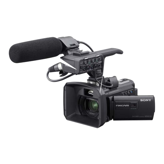
Photo: HXR-NX30U
Digital HD Video Camera Recorder
Ver.
Date
1.0
2012.05
1.1
2012.06
US Model
AEP Model
E Model
Sony Corporation
Revision History
History
Contents
Official Release
—
Revised-1
• Revision of SPECIFICATIONS.
(A1 12-118)
Page
3
• Revision of REPAIR PARTS LIST.
Page
2-7
• Revision of ASSEMBLY.
Page
3-1
983467512.pdf
S.M. Rev.
issued
—
Yes
2012F08-1
© 2012.06
Published by Sony Techno Create Corporation
Advertisement
Table of Contents

Related Manuals for Sony NX30J


Summarization of Contents
Service Manual
Revision History
Records changes made to the service manual over different versions.
Service Notes
Important notes and precautions to check before performing service or repairs.
English Service Procedures
List of service procedures and precautions for English-speaking users.
Japanese Service Procedures
List of service procedures and precautions for Japanese-speaking users.
Product Specifications
System Specifications
General system and signal format details of the camera recorder.
Input/Output Connectors
Details of the available input and output connectors on the device.
LCD Screen Specifications
Technical details about the device's LCD screen.
Projector Specifications
Technical details about the integrated projector function.
General Specifications
General operational parameters like power requirements and temperature.
AC Adaptor Specifications
Specifications for the AC power adapter used with the device.
Rechargeable Battery Pack Specifications
Specifications for the NP-FV70 rechargeable battery pack.
Model Information Table
Model Variants
Lists different model numbers and their corresponding destinations and color systems.
Model Destination Information
Information about the destination markets for each model variant.
Color System Specifications
Specifies the color system (PAL/NTSC) for each model.
Recording Media Details
Details about the internal memory and compatible recording media.
Lens Specifications
Information about the Carl Zeiss Vario-Sonnar T* lens.
Projector Functionality
Indicates whether the projector function is available for each model.
GPS Functionality
Indicates whether GPS functionality is available for each model.
Electronic Viewfinder Availability
Indicates if an electronic viewfinder is included in the model.
Hot Shoe Availability
Indicates if a hot shoe is present on the model.
Charging Capacitor (for flash)
Notes about the charging capacitor for the flash unit.
Model Group Information
Groups models based on GPS functionality.
Safety Check-out Procedure
General Safety Checks
Steps to perform after service to ensure safe operation of the device.
Unleaded Solder Information
Information about the use of unleaded solder and its associated marks.
Lead Free Mark Explanation
Identification and explanation of the lead-free mark on PCBs.
Service Notes
Power Supply During Repairs
Method to prevent automatic power shut-off during repairs.
VC-658 Board Replacement Precautions
Precautions and procedures for replacing the VC-658 board.
Destination Data Handling
Procedures for handling destination data when replacing the board.
USB Serial Data Save
Procedure to save USB serial data before board replacement.
USB Serial Number Input
Procedure for entering the USB serial number after board replacement.
Projector Data Acquisition
How to acquire fixed value and serial number for the projector.
Internal Memory Model Procedures
Procedures for units with internal memory after board replacement.
Adding Destination Data Files
Obtaining New Destination Data from TISS
Steps to download updated destination data files from the TISS homepage.
Executing Destination Data Write
Steps to execute the destination data write process using the Adjust manual.
LD-297 Board Replacement Precautions
Angular Velocity Sensor Adjustment
How to record and adjust the angular velocity sensor sensitivity.
Self-Diagnosis Function
Self-Diagnosis Function Overview
Description of the self-diagnosis function and its displays.
Self-Diagnosis Display Details
Explanation of the 4-digit self-diagnosis code displayed on the LCD.
Self-Diagnosis Code Table
Table listing self-diagnosis codes, symptoms, and correction procedures.
Shift Lens Error Troubleshooting
Abnormality of IC for Steadyshot (E:62:02)
Troubleshooting procedure for IC abnormality related to steadyshot function.
Shift Lens Overheating (Pitch) Error (E:62:11)
Troubleshooting steps for shift lens overheating (pitch) errors.
Shift Lens Error Troubleshooting
Shift Lens Overheating (Yaw) Error (E:62:12)
Troubleshooting steps for shift lens overheating (yaw) errors.
Thermistor Abnormality Error (E:62:20)
Troubleshooting procedure for thermistor abnormalities.
GPS Signal Reception Check
Procedure to check GPS signal reception after assembly or part replacement.
Checking GPS Functionality
Steps to verify the GPS function by triangulating satellite signals.
Using GPS Assist Data
How to use GPS Assist Data to shorten location acquisition time.
Projector Unit Replacement Notes
Projector Problem Checking (Brightness)
Flowchart for troubleshooting projector issues, excluding brightness.
Projector Problem Checking (Brightness Indication)
Flowchart for troubleshooting projector issues related to brightness indication.
Cabinet (Bottom) Replacement Precautions
Ordering Cabinet (Bottom) Parts
Guidance on selecting the correct bottom cabinet part number based on the model.
HXR-NX30J Cabinet (Bottom) Replacement
Specific instructions for replacing the bottom cabinet on the HXR-NX30J model.
HXR-NX30U Cabinet (Bottom) Replacement
Specific instructions for replacing the bottom cabinet on the HXR-NX30U model.
HXR-NX30N Cabinet (Bottom) Replacement
Specific instructions for replacing the bottom cabinet on the HXR-NX30N model.
Power Supply During Repairs (Japanese)
Method: Use AC Adapter
Method to prevent automatic power shut-off during repairs.
Destination Data Handling (Japanese)
Procedures for handling destination data when replacing the board.
USB Serial Data Save (Japanese)
Procedure to save USB serial data before board replacement.
USB Serial Number Input (Japanese)
Procedure for entering the USB serial number after board replacement.
Projector Data Acquisition (Japanese)
How to acquire fixed value and serial number for the projector.
Internal Memory Model Procedures (Japanese)
Procedures for units with internal memory after board replacement.
Adding Destination Data Files (Japanese)
Obtain New Destination Data from TISS (Japanese)
Steps to download updated destination data files from the TISS homepage.
Download and Unzip Destination Data (Japanese)
Download and extract the destination data file for the relevant model.
Execute Destination Data Write (Japanese)
Steps to execute the destination data write process using the Adjust manual.
LD-297 Board Replacement Precautions (Japanese)
Angular Velocity Sensor Adjustment (Japanese)
How to record and adjust the angular velocity sensor sensitivity.
Self-Diagnosis Function (Japanese)
Self-Diagnosis Function Overview (Japanese)
Description of the self-diagnosis function and its displays.
Self-Diagnosis Display Details (Japanese)
Explanation of the 4-digit self-diagnosis code displayed on the LCD.
Self-Diagnosis Code Table (Japanese)
Table listing self-diagnosis codes, symptoms, and correction procedures.
Shift Lens Error Troubleshooting (Japanese)
Steadyshot IC Abnormality (E:62:02) (Japanese)
Troubleshooting procedure for IC abnormality related to steadyshot function.
Shift Lens Overheating (Pitch) Error (E:62:11) (Japanese)
Troubleshooting steps for shift lens overheating (pitch) errors.
Shift Lens Error Troubleshooting (cont.) (Japanese)
Shift Lens Overheating (Yaw) Error (E:62:12) (Japanese)
Troubleshooting steps for shift lens overheating (yaw) errors.
Thermistor Abnormality Error (E:62:20) (Japanese)
Troubleshooting procedure for thermistor abnormalities.
GPS Signal Reception Check (Japanese)
Procedure to check GPS signal reception after assembly or part replacement.
Checking GPS Functionality (Japanese)
Steps to verify the GPS function by triangulating satellite signals.
Using GPS Assist Data (Japanese)
How to use GPS Assist Data to shorten location acquisition time.
Projector Unit Replacement Notes (Japanese)
Projector Problem Checking (Brightness) (Japanese)
Flowchart for troubleshooting projector issues, excluding brightness.
Projector Problem Checking (Brightness Indication) (Japanese)
Flowchart for troubleshooting projector issues related to brightness indication.
Cabinet (Bottom) Replacement Precautions (Japanese)
Ordering Cabinet (Bottom) Parts (Japanese)
Guidance on selecting the correct bottom cabinet part number based on the model.
HXR-NX30J Cabinet (Bottom) Replacement (Japanese)
Specific instructions for replacing the bottom cabinet on the HXR-NX30J model.
HXR-NX30U Cabinet (Bottom) Replacement (Japanese)
Specific instructions for replacing the bottom cabinet on the HXR-NX30U model.
HXR-NX30N Cabinet (Bottom) Replacement (Japanese)
Specific instructions for replacing the bottom cabinet on the HXR-NX30N model.
Repair Parts List
Identifying Parts
Visual guide to identify major components and their locations on the camera.
English Notes for Parts List
General notes and explanations for the English parts list section.
Japanese Notes for Parts List
General notes and explanations for the Japanese parts list section.
Appearance Part Color Indication
Explains color coding for external parts like cabinets and parts.
Part View Positions
Illustrates different viewing angles for identifying parts.
Repair Notes for Cables and Connectors
General Repair Precautions (English)
Precautions for handling flat cables, flexible boards, and connectors during repair.
General Repair Precautions (Japanese)
Precautions for handling flat cables, flexible boards, and connectors during repair.
Exploded Views
Overall Section 1 Exploded View
Exploded view of the main body of the camera, showing overall component layout.
Disassembly Procedure
Step-by-step instructions for disassembling the camera unit.
Screw Handling Notes
Important notes regarding screw types and replacement during disassembly.
Overall Section 2 Exploded View
Disassembly Procedure (Section 2)
Step-by-step instructions for disassembling the camera unit, continuing from Section 1.
Screw Handling Notes
Important notes regarding screw types and replacement during disassembly.
BT Panel Section Exploded View
BT Panel Disassembly Procedure
Step-by-step instructions for disassembling the BT panel section.
Main Board Section Exploded View
Disassembly Procedure
Step-by-step instructions for disassembling the main board.
Screw Handling Notes
Important notes regarding screw types and replacement during disassembly.
Battery Replacement Caution
Safety warning regarding battery replacement and disposal.
Lens Section Exploded View
Disassembly Procedure
Step-by-step instructions for disassembling the lens section.
Imager Replacement Notes
Precautions to read before changing the imager.
Lens Device Handling Caution
Specific caution for handling the lens device, especially regarding orientation.
Cabinet (F) Section Exploded View
Cabinet (F) Section Disassembly Procedure
Step-by-step instructions for disassembling the cabinet (F) section.
LCD Section 1 Exploded View
Disassembly Procedure
Step-by-step instructions for disassembling the LCD section 1.
Screw Handling Notes
Important notes regarding screw types and replacement during disassembly.
Screw Reuse Caution
Warning against reusing removed screws; use new screws for repair.
Part Handling Caution
Caution regarding handling specific parts, especially those that get hot after use.
LCD Section 2 Exploded View
Disassembly Procedure
Step-by-step instructions for disassembling the LCD section 2.
Screw Handling Notes
Important notes regarding screw types and replacement during disassembly.
Magnet Installation Orientation
Instructions on correctly orienting the magnet when installing it.
FP-1519 Flexible Board Attachment
Reference to assembly instructions for the FP-1519 flexible board.
XLR Section Exploded View
Disassembly Procedure
Step-by-step instructions for disassembling the XLR section.
XLR Label Note
Note regarding XLR labels not being included with the XLR unit block assembly.
Included Accessories
Accessories (Except J Model)
List of accessories included with models other than the J model.
Accessories (J Model)
List of accessories included with the J model.
Accessory Not Supplied as Service Part
Information that certain accessories are not available as service parts.
Accessory Not Supplied as Service Part (Japanese)
Information that certain accessories are not available as service parts.
Schematic Diagrams and Printed Wiring Boards
Imager Replacement Precautions
Important precautions to follow when replacing the imager.
Part Reference Numbering
Instruction on how to correctly specify parts using reference numbers and board names.
Schematic Diagram Notes
General notes and conventions used in schematic diagrams.
Printed Wiring Board Notes
General notes and conventions used in printed wiring board diagrams.
Electrical Parts List
Comprehensive list of electrical components with part numbers and specifications.
Electrical Parts List (Continued)
Capacitors List (C7701-C7707)
List of capacitors and their specifications.
Connectors List (CN9001, CN9002)
List of connectors and their specifications.
Diodes List (D9001, D9002)
List of diodes and their specifications.
Integrated Circuits List (IC7701)
List of integrated circuits and their specifications.
Coils List (L7701)
List of coils and their specifications.
Resistors List (R7702-R9012)
List of resistors and their specifications.
Composition Circuit Blocks (RB9001, RB9002)
List of composition circuit blocks and their specifications.
Switches List (S9001-S9006)
List of switches and their specifications.
Sensors List (SE7701)
List of sensors and their specifications.
Electrical Parts List (Continued)
Capacitors List (Various)
List of various capacitors and their specifications.
Connectors List (Various)
List of various connectors and their specifications.
Diodes List (Various)
List of various diodes and their specifications.
Integrated Circuits List (Various)
List of various integrated circuits and their specifications.
Coils List (Various)
List of various coils and their specifications.
Transistors List (Various)
List of various transistors and their specifications.
Resistors List (Various)
List of various resistors and their specifications.
Line Filters List (Various)
List of line filters and their specifications.
Electrical Parts List (Continued)
Capacitors List (Various)
List of various capacitors and their specifications.
Connectors List (Various)
List of various connectors and their specifications.
Diodes List (Various)
List of various diodes and their specifications.
Fuses List (F001-F009)
List of fuses and their specifications.
Ferrite Beads List (Various)
List of ferrite beads and their specifications.
Integrated Circuits List (Various)
List of various integrated circuits and their specifications.
Coils List (Various)
List of various coils and their specifications.
Transistors List (Various)
List of various transistors and their specifications.
Resistors List (Various)
List of various resistors and their specifications.
Electrical Parts List (Continued)
Capacitors List (Various)
List of various capacitors and their specifications.
Connectors List (Various)
List of various connectors and their specifications.
Diodes List (Various)
List of various diodes and their specifications.
Integrated Circuits List (Various)
List of various integrated circuits and their specifications.
Coils List (Various)
List of various coils and their specifications.
Transistors List (Various)
List of various transistors and their specifications.
Resistors List (Various)
List of various resistors and their specifications.
Electrical Parts List (Continued)
Resistors List (Various)
List of various resistors and their specifications.
Composition Circuit Blocks (Various)
List of various composition circuit blocks and their specifications.
VC-658 Board (Service) Parts
List of service-specific parts for the VC-658 board.
Capacitors List (Various)
List of various capacitors and their specifications.
Electrical Parts List (Continued)
Resistors List (Various)
List of various resistors and their specifications.
XL-013 Parts List
List of parts related to the XL-013 connector/board.
Assembly Instructions
USB Arm Retainer Installation Cautions
Cautions for installing the USB arm retainer, including routing the microphone harness.
VF Flexible Guard Installation Cautions
Cautions for installing the VF flexible guard.
CM Flexible Guard Installation Cautions
Cautions for installing the CM flexible guard.
Lens Ornament Removal Method
Step-by-step guide on how to remove the lens ornament.
Lens Device Handling Caution
Specific caution for handling the lens device, especially regarding orientation.
Lens Device Orientation Caution
Caution against turning the lens device downward during handling.
FP-1519 Flexible Board Attachment Method
FP-1519 Flexible Board Attachment Steps
Detailed steps for attaching the FP-1519 flexible board.
LCD Cushion Installation Cautions
Applying LCD Cushion
Steps for applying the LCD cushion, including peeling off the release paper.
Block Diagrams
Overall Block Diagram (1/5)
High-level block diagram showing the main functional units and their interconnections.
Overall Block Diagram (2/5)
Touch Panel Interface Block
Block diagram showing the touch panel interface.
LCD Module Block
Block diagram for the LCD module.
PD-465 Board Block Diagram
Block diagram for the PD-465 board.
PJ-104 Board Block Diagram
Block diagram for the PJ-104 board.
FP-1519 Flexible Board Block Diagram
Block diagram for the FP-1519 flexible board.
FP-1582 Flexible Board Block Diagram
Block diagram for the FP-1582 flexible board.
DMD Control Block Diagram
Block diagram illustrating the DMD control signals.
LED Decoder Block Diagram
Block diagram illustrating the LED decoder functionality.
SDRAM Block Diagram
Block diagram showing the SDRAM connections.
Inverter Block Diagram
Block diagram illustrating the inverter circuit.
LED Drive Block Diagram
Block diagram showing the LED drive circuitry.
Overall Block Diagram (3/5)
MIC AMP IC2201 Block
Block diagram for the MIC AMP IC2201.
XLR Unit Block
Block diagram showing the XLR unit.
MIC AMP IC2202 Block
Block diagram for the MIC AMP IC2202.
LINE AMP IC2203 Block
Block diagram for the LINE AMP IC2203.
MPU IC1001 Block
Block diagram for the MPU IC1001.
Control Switch Block (AU91000)
Block diagram for the control switch block.
Overall Block Diagram (4/5)
LD-297 Board Block Diagram (1/2)
Block diagram for the LD-297 board, part 1 of 2.
VC-658 Board Block Diagram (2/3)
Block diagram for the VC-658 board, part 2 of 3.
Control Switch Block (RS39900)
Block diagram for the control switch block.
FP-1518 Flexible Board Block Diagram
Block diagram for the FP-1518 flexible board.
FP-1521 Flexible Board Block Diagram
Block diagram for the FP-1521 flexible board.
FP-1550 Flexible Board Block Diagram
Block diagram for the FP-1550 flexible board.
FP-1555 Flexible Board Block Diagram
Block diagram for the FP-1555 flexible board.
Lens Block Diagram
Block diagram representing the lens assembly.
Overall Block Diagram (5/5)
LD-297 Board Block Diagram (1/2)
Block diagram for the LD-297 board, part 1 of 2.
VC-658 Board Block Diagram (2/3)
Block diagram for the VC-658 board, part 2 of 3.
Memory Card Interface Block
Block diagram showing the interface for memory stick and SD cards.
Control Switch Block (RS39900)
Block diagram for the control switch block.
FR-319 Board Block Diagram
Block diagram for the FR-319 board.
FP-1518 Flexible Board Block Diagram
Block diagram for the FP-1518 flexible board.
FP-1521 Flexible Board Block Diagram
Block diagram for the FP-1521 flexible board.
Power Block Diagram (1/4)
Battery Terminal Power Block
Block diagram illustrating power supply from the battery terminal.
DC/DC Converter IC4301 Block
Block diagram for the DC/DC converter IC4301.
B+ Switch IC4304 Block
Block diagram for the B+ switch IC4304.
BL Drive IC4303 Block
Block diagram for the BL drive IC4303.
DC/DC Converter, LANC Driver IC4302 Block
Block diagram for the DC/DC converter and LANC driver IC4302.
USB Power Management IC9101 Block
Block diagram for the USB power management IC9101.
Smart Power Selector IC9102 Block
Block diagram for the smart power selector IC9102.
USB Switch IC9103 Block
Block diagram for the USB switch IC9103.
Current Limiter IC9105 Block
Block diagram for the current limiter IC9105.
USB Switch IC9104 Block
Block diagram for the USB switch IC9104.
Power Block Diagram (2/4)
PD-465 Board Power Block Diagram
Block diagram showing power distribution on the PD-465 board.
FP-1582 Flexible Board Power Block Diagram
Block diagram showing power distribution on the FP-1582 flexible board.
PJ-104 Board Power Block Diagram
Block diagram showing power distribution on the PJ-104 board.
GP-037 Board Power Block Diagram
Block diagram showing power distribution on the GP-037 board.
FP-1519 Flexible Board Power Block Diagram
Block diagram showing power distribution on the FP-1519 flexible board.
VC-658 Board Power Block Diagram (2/3)
Block diagram showing power distribution on the VC-658 board, part 2 of 3.
RH-014 Board Power Block Diagram
Block diagram showing power distribution on the RH-014 board.
Power Block Diagram (3/4)
VC-658 Board Power Block Diagram (3/3)
Block diagram showing power distribution on the VC-658 board, part 3 of 3.
FP-1523 Flexible Board Power Block Diagram
Block diagram showing power distribution on the FP-1523 flexible board.
FP-1518 Flexible Board Power Block Diagram
Block diagram showing power distribution on the FP-1518 flexible board.
HN-003 Board Power Block Diagram
Block diagram showing power distribution on the HN-003 board.
XL-013 Board Power Block Diagram
Block diagram showing power distribution on the XL-013 board.
Power Block Diagram (4/4)
HN-003 Board Power Block Diagram
Block diagram showing power distribution on the HN-003 board.
XL-013 Board Power Block Diagram
Block diagram showing power distribution on the XL-013 board.
Assembly Instructions
USB Arm Retainer Installation Cautions
Cautions for installing the USB arm retainer, including routing the microphone harness.
VF Flexible Guard Installation Cautions
Cautions for installing the VF flexible guard.
CM Flexible Guard Installation Cautions
Cautions for installing the CM flexible guard.
Lens Ornament Removal Method
Step-by-step guide on how to remove the lens ornament.
Frame Schematic Diagrams (2/2)
FP-1582 Flexible Board Note
Note about FP-1582 Flexible Complete Board not being supplied separately.
VC-658 Board (Side B) Frame Schematic
Frame schematic of the VC-658 board, side B.
FR-319 Board (Side A) Frame Schematic
Frame schematic of the FR-319 board, side A.
FR-319 Board (Side B) Frame Schematic
Frame schematic of the FR-319 board, side B.
LD-297 Board (Side A) Frame Schematic
Frame schematic of the LD-297 board, side A.
LD-297 Board (Side B) Frame Schematic
Frame schematic of the LD-297 board, side B.
PD-465 Board Frame Schematic
Frame schematic of the PD-465 board.
PJ-104 Board (Side B) Frame Schematic
Frame schematic of the PJ-104 board, side B.
PJ-104 Board (Side A) Frame Schematic
Frame schematic of the PJ-104 board, side A.
GP-037 Board (Side B) Frame Schematic
Frame schematic of the GP-037 board, side B.
GP-037 Board (Side A) Frame Schematic
Frame schematic of the GP-037 board, side A.
Schematic Diagrams and Printed Wiring Boards
Imager Replacement Precautions
Important precautions to follow when replacing the imager.
Part Reference Numbering
Instruction on how to correctly specify parts using reference numbers and board names.
Schematic Diagram Notes
General notes and conventions used in schematic diagrams.
Printed Wiring Board Notes
General notes and conventions used in printed wiring board diagrams.
Schematic Diagrams
XCLR Schematic
Schematic diagram for the XCLR signal.
XHS Schematic
Schematic diagram for the XHS signal.
XVS Schematic
Schematic diagram for the XVS signal.
IC and Board Supply Note
Note regarding the supply status of IC6701 and CM-121 board.
Schematic Diagrams (Continued)
XSYS_RST Schematic
Schematic diagram for the XSYS_RST signal.
XFLASH_RST Schematic
Schematic diagram for the XFLASH_RST signal.
XBB_RST Schematic
Schematic diagram for the XBB_RST signal.
XPJ_RESET Schematic
Schematic diagram for the XPJ_RESET signal.
XGPS_RST Schematic
Schematic diagram for the XGPS_RST signal.
Schematic Diagrams (Continued)
LD-297 Board Schematic (2/5)
Schematic diagram for the LD-297 board, part 2 of 5.
Iris/ND/Zoom/Focus Drive Signals
Signals related to the iris, ND, zoom, and focus drives.
Schematic Diagrams (Continued)
LD-297 Board Schematic (3/5)
Schematic diagram for the LD-297 board, part 3 of 5.
Lens Control Signals
Signals and components related to lens control.
Schematic Diagrams (Continued)
LD-297 Board Schematic (4/5)
Schematic diagram for the LD-297 board, part 4 of 5.
Pitch/Yaw Sensor Signals
Signals related to the pitch and yaw sensor.
Schematic Diagrams (Continued)
LD-297 Board Schematic (5/5)
Schematic diagram for the LD-297 board, part 5 of 5.
Memory Card Slot Signals
Signals related to the memory card slot.
RH-014 Board Schematic (4/5)
Schematic diagram for the RH-014 board, part 4 of 5.
FP-1555 Flexible Board Note
Note about FP-1555 Flexible Complete Board not being supplied separately.
Flexible Board VC-LD Connection
VC-658 Board (1/10) CN1001 Connection
Connection details between VC-658 board CN1001 and flexible board.
VC-658 Board (1/10) CN1002 Connection
Connection details between VC-658 board CN1002 and flexible board.
LD-297 Board (1/5) CN4001 Connection
Connection details between LD-297 board CN4001 and flexible board.
FP-1550 Flexible Board VC-LD Connection
Connection schematic for FP-1550 flexible board to VC-LD.
FP-1551 Flexible Board VC-LD Connection
Connection schematic for FP-1551 flexible board to VC-LD.
Schematic Diagrams
VC-658 Board (1/10) CN1005 Connection
Connection details between VC-658 board CN1005 and flexible board.
VC-658 Board (1/10) CN1006 Connection
Connection details between VC-658 board CN1006 and flexible board.
PD-465 Board (1/2) CN6001 Connection
Connection details between PD-465 board CN6001 and flexible board.
FP-1519 Flexible Board Connection Schematic
Connection schematic for FP-1519 flexible board.
FP-1518 Flexible Board Connection Schematic
Connection schematic for FP-1518 flexible board.
Schematic Diagrams (Continued)
VC-658 Board Schematic (2/10)
Schematic diagram for the VC-658 board, part 2 of 10.
CPU, AV Signal, Lens, Mode, HDMI Process (1/3)
Schematic details for CPU, AV signal processing, lens control, mode control, and HDMI.
IC1301 Supply Note
Note regarding IC1301 not being supplied separately but included in the complete board.
Schematic Diagrams (Continued)
VC-658 Board Schematic (3/10)
Schematic diagram for the VC-658 board, part 3 of 10.
CPU, AV Signal, Lens, Mode, HDMI Process (2/3)
Schematic details for CPU, AV signal processing, lens control, mode control, and HDMI.
IC1301 Supply Note
Note regarding IC1301 not being supplied separately but included in the complete board.
Schematic Diagrams (Continued)
VC-658 Board Schematic (4/10)
Schematic diagram for the VC-658 board, part 4 of 10.
CPU, AV Signal, Lens, Mode, HDMI Process (3/3)
Schematic details for CPU, AV signal processing, lens control, mode control, and HDMI.
IC1301 Supply Note
Note regarding IC1301 not being supplied separately but included in the complete board.
Schematic Diagrams (Continued)
VC-658 Board Schematic (5/10)
Schematic diagram for the VC-658 board, part 5 of 10.
Speaker Amplifier Circuit
Schematic diagram for the speaker amplifier circuit.
Schematic Diagrams (Continued)
VC-658 Board Schematic (6/10)
Schematic diagram for the VC-658 board, part 6 of 10.
AUDIO DSP (Not used) Schematic
Schematic diagram for the unused audio DSP.
FP-1557 FLEXIBLE BOARD VC-MM CONECTION
Connection schematic for FP-1557 flexible board to VC-MM.
Schematic Diagrams (Continued)
VC-658 Board Schematic (7/10)
Schematic diagram for the VC-658 board, part 7 of 10.
SERIALIZER
Schematic diagram for the serializer component.
Schematic Diagrams (Continued)
VC-658 Board Schematic (8/10)
Schematic diagram for the VC-658 board, part 8 of 10.
DC/DC CONVERTER
Schematic diagram of the DC/DC converter circuits.
Schematic Diagrams (Continued)
VC-658 Board Schematic (9/10)
Schematic diagram for the VC-658 board, part 9 of 10.
HI CONTROL
Schematic diagram for the HI control system.
Schematic Diagrams (Continued)
VC-658 Board Schematic (10/10)
Schematic diagram for the VC-658 board, part 10 of 10.
USB INTERFACE
Schematic diagram for the USB interface.
Schematic Diagrams (Continued)
MM-102 BOARD (1/2)
Schematic diagram for the MM-102 board, part 1 of 2.
INTERNAL MEMORY
Schematic diagram of the internal memory components.
Schematic Diagrams (Continued)
MM-102 BOARD (2/2)
Schematic diagram for the MM-102 board, part 2 of 2.
INTERNAL MEMORY
Schematic diagram of the internal memory components.
Schematic Diagrams (Continued)
RH-014 BOARD (1/5)
Schematic diagram for the RH-014 board, part 1 of 5.
MIC/HP AMP
Schematic diagram for the MIC/HP amplifier circuit.
Schematic Diagrams (Continued)
RH-014 BOARD (2/5)
Schematic diagram for the RH-014 board, part 2 of 5.
VIDEO/AUDIO PROCESSOR
Schematic diagram of the video/audio processor.
Schematic Diagrams (Continued)
RH-014 BOARD (3/5)
Schematic diagram for the RH-014 board, part 3 of 5.
LEVEL SHIFT
Schematic diagram for the level shift circuits.
Schematic Diagrams (Continued)
RH-014 BOARD (4/5)
Schematic diagram for the RH-014 board, part 4 of 5.
CONNECTORS
Schematic diagram showing various connectors.
Schematic Diagrams (Continued)
RH-014 BOARD (5/5)
Schematic diagram for the RH-014 board, part 5 of 5.
LED FLASH DRIVE
Schematic diagram for the LED flash drive circuit.
FR-319 BOARD (SIDE A)
FR-319 BOARD (SIDE B)
Printed wiring board layout for FR-319 board, side B.
Q9601 is not supplied, but this is included in FR-319 COMPLETE BOARD.
Note regarding Q9601 not being supplied separately but included in the complete board.
CK-244 BOARD (SIDE A)
CK-244 BOARD (SIDE B)
Printed wiring board layout for CK-244 board, side B.
FP-1521 FLEXIBLE BOARD VC-CK CONNECTION
Connection schematic for FP-1521 flexible board to VC-CK.
CK-244 BOARD (2/2)
CONTROL KEYS
Schematic diagram for the control keys.
CONTROL SWITCH BLOCK (PS39900) is not included in CK-244 COMPLETE BOARD.
Note about CONTROL SWITCH BLOCK (PS39900) not being supplied separately.
PD-465 BOARD (1/2)
LCD
Schematic diagram related to the LCD.
Note: All mounted parts are not supplied, but they are included in PJ-104 COMPLETE BOARD.
Note about parts not being supplied separately but included in the PJ-104 board.
PJ-104 BOARD (1/4)
CONNECTORS, REGULATOR
Schematic diagram of connectors and regulators.
Note: All mounted parts are not supplied, but they are included in PJ-104 COMPLETE BOARD.
Note about parts not being supplied separately but included in the PJ-104 board.
Note: PROJECTOR UNIT is not included in FP-1582 FLEXIBLE COMPLETE BOARD.
Note about the projector unit not being supplied separately.
PJ-104 BOARD (2/4)
DMD CONTROL
Schematic diagram for DMD control.
Note: All mounted parts are not supplied, but they are included in PJ-104 COMPLETE BOARD.
Note about parts not being supplied separately but included in the PJ-104 board.
PJ-104 BOARD (3/4)
SDRAM
Schematic diagram for SDRAM.
Note: All mounted parts are not supplied, but they are included in PJ-104 COMPLETE BOARD.
Note about parts not being supplied separately but included in the PJ-104 board.
PJ-104 BOARD (4/4)
LED DRIVE
Schematic diagram for LED drive circuitry.
Note: All mounted parts are not supplied, but they are included in PJ-104 COMPLETE BOARD.
Note about parts not being supplied separately but included in the PJ-104 board.
GP-037 BOARD (SIDE A)
GP-037 BOARD (SIDE B)
Printed wiring board layout for GP-037 board, side B.
Note: All mounted parts and GP-037 COMPLETE BOARD are not supplied, but they are included in GP386 ASSY.
Note about parts not being supplied separately but included in GP386 ASSY.
FP-1582 FLEXIBLE BOARD
PJ-PROJECTOR CONNECTION
Connection schematic between FP-1582 flexible board and projector.
Note: All mounted parts are not supplied, but they are included in FP-1582 FLEXIBLE COMPLETE BOARD.
Note about parts not being supplied separately but included in FP-1582 board.
Note: PROJECTOR UNIT is not included in FP-1582 FLEXIBLE COMPLETE BOARD.
Note about the projector unit not being supplied separately.
FP-1554 FLEXIBLE BOARD
Note: All mounted parts are not supplied, but they are included in FP-1554 FLEXIBLE COMPLETE BOARD.
Note about parts not being supplied separately but included in FP-1554 board.
FP-1555 FLEXIBLE BOARD
Note: FP-1555 FLEXIBLE COMPLETE BOARD is not supplied, but this is included in ST LED BLOCK ASSY.
Note about FP-1555 Flexible Complete Board not being supplied separately.
HN-003 BOARD (SIDE A)
HN-003 BOARD (SIDE B)
Printed wiring board layout for HN-003 board, side B.
Note: CONTROL SWITCH BLOCK (AU91000) and ENCAPSULATED CABLE are not included in HN-003 COMPLETE BOARD.
Note about parts not being supplied separately but included in HN-003 board.
XL-013 BOARD (SIDE A)
XL-013 BOARD (SIDE B)
Printed wiring board layout for XL-013 board, side B.
Note: IC2301 is not supplied, but this is included in XL-013 COMPLETE BOARD.
Note about IC2301 not being supplied separately but included in the complete board.
Printed Wiring Boards
CM-121 BOARD (SIDE A)
Printed wiring board layout for CM-121 board, side A.
CM-121 BOARD (SIDE B)
Printed wiring board layout for CM-121 board, side B.
Note: IC6701 and CM-121 COMPLETE BOARD are not supplied, but they are included in CMOS BLOCK ASSY (1390)-077.
Note about IC6701 and CM-121 board not being supplied separately.
Schematic Diagrams (Continued)
LD-297 BOARD (SIDE A)
Schematic diagram of the LD-297 board, side A.
LD-297 BOARD (SIDE B)
Schematic diagram of the LD-297 board, side B.
Note: IC5602, IC5603, IC5609, IC5611 and L5601 are not supplied, but they are included in LD-297 COMPLETE BOARD.
Note about ICs and L5601 not being supplied separately.
Schematic Diagrams (Continued)
FR-319 BOARD (SIDE A)
Schematic diagram of the FR-319 board, side A.
FR-319 BOARD (SIDE B)
Schematic diagram of the FR-319 board, side B.
Note: Q9601 is not supplied, but this is included in FR-319 COMPLETE BOARD.
Note about Q9601 not being supplied separately but included in the complete board.
Schematic Diagrams (Continued)
CK-244 BOARD (SIDE A)
Schematic diagram of the CK-244 board, side A.
CK-244 BOARD (SIDE B)
Schematic diagram of the CK-244 board, side B.
FP-1521 FLEXIBLE BOARD VC-CK CONNECTION
Connection schematic for FP-1521 flexible board to VC-CK.
Schematic Diagrams (Continued)
Note: BT7001 and C7207 are not included in RH-014 COMPLETE BOARD.
Note about BT7001 and C7207 not being included in the RH-014 board.
Note: IC6401 is not supplied, but this is included in RH-014 COMPLETE BOARD.
Note about IC6401 not being supplied separately but included in the RH-014 board.
Schematic Diagrams (Continued)
FR-319 BOARD (SIDE A)
Schematic diagram of the FR-319 board, side A.
FR-319 BOARD (SIDE B)
Schematic diagram of the FR-319 board, side B.
Note: Q9601 is not supplied, but this is included in FR-319 COMPLETE BOARD.
Note about Q9601 not being supplied separately but included in the complete board.
Schematic Diagrams (Continued)
PD-465 BOARD
Schematic diagram of the PD-465 board.
Schematic Diagrams (Continued)
PJ-104 BOARD (SIDE B)
Schematic diagram of the PJ-104 board, side B.
PJ-104 BOARD (SIDE A)
Schematic diagram of the PJ-104 board, side A.
Note: All mounted parts are not supplied, but they are included in PJ-104 COMPLETE BOARD.
Note about parts not being supplied separately but included in the PJ-104 board.
Schematic Diagrams (Continued)
FP-1554 FLEXIBLE BOARD
Schematic diagram of the FP-1554 flexible board.
Note: All mounted parts are not supplied, but they are included in FP-1554 FLEXIBLE COMPLETE BOARD.
Note about parts not being supplied separately but included in FP-1554 board.
FP-1555 FLEXIBLE BOARD
Schematic diagram of the FP-1555 flexible board.
Note: FP-1555 FLEXIBLE COMPLETE BOARD is not supplied, but this is included in ST LED BLOCK ASSY.
Note about FP-1555 Flexible Complete Board not being supplied separately.
FP-1582 FLEXIBLE BOARD
Schematic diagram of the FP-1582 flexible board.
Schematic Diagrams (Continued)
HN-003 BOARD (SIDE A)
Schematic diagram of the HN-003 board, side A.
HN-003 BOARD (SIDE B)
Schematic diagram of the HN-003 board, side B.
Note: CONTROL SWITCH BLOCK (AU91000) and ENCAPSULATED CABLE are not included in HN-003 COMPLETE BOARD.
Note about parts not being supplied separately but included in HN-003 board.
Need help?
Do you have a question about the NX30J and is the answer not in the manual?
Questions and answers