Table of Contents
Advertisement
Quick Links
SERVICE MANUAL
Ver. 1.1 2012.06
Revised-1
Replace the previously issued
SERVICE MANUAL 9-834-675-11
with this Manual.
SERVICE NOTE (Check the following note before the service.)
– ENGLISH –
1-1.
POWER SUPPLY DURING REPAIRS
1-2.
PRECAUTION ON REPLACING THE VC-658 BOARD
1-3.
ADDITION OF DESTINATION DATA FILE
1-4.
PRECAUTION ON REPLACING THE LD-297 BOARD
1-5.
SELF-DIAGNOSIS FUNCTION
1-6.
METHOD OF COPING WITH SHIFT LENS ERROR
1-7.
GPS RECEIVING CHECK (NX30E/NX30J/NX30N/NX30P/NX30U)
1-8.
DISCHARGE OF LED FLASH/VIDEO LIGHT
1-9.
NOTE ON REPLACING PROJECTOR UNIT
1-10.
PRECAUTION ON REPLACING THE CABINET (BOTTOM)
‒ JAPANESE ‒
1-1.
修理時の電源供給について
1-2.
VC-658基板交換時の注意
1-3.
Destination Data ファイルの追加について
1-4.
LD-297基板交換時の注意
1-5.
自己診断機能
1-6.
シフトレンズエラーの対処方法
1-7.
GPS 受信確認 (NX30E/NX30J/NX30N/NX30P/NX30U)
1-8.
LEDフラッシュ/ビデオライトの放電について
1-9.
プ ロジェクターユニット交換時の注意
1-10.
キャビネット (底) 交換時の注意
The components identified by mark
Les composants identifiés par une
0 or dotted line with mark 0 are
marque 0 sont critiques pour la
critical for safety.
sécurité.
Replace only with part number
Ne les remplacer que par une
specified.
pièce portant le numéro spécifié.
HXR-NX30C/NX30E/NX30J/NX30N/NX30P/NX30U
9-834-675-12
HXR-NX30C/NX30E/NX30J/
NX30N/NX30P/NX30U
Canadian Model
Chinese Model
Japanese Model
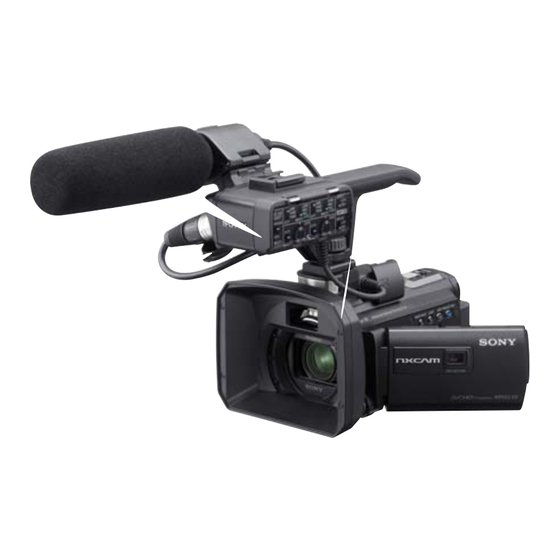
Photo: HXR-NX30U
Digital HD Video Camera Recorder
Ver.
Date
1.0
2012.05
1.1
2012.06
US Model
AEP Model
E Model
Sony Corporation
Revision History
History
Contents
Official Release
—
Revised-1
• Revision of SPECIFICATIONS.
(A1 12-118)
Page
3
• Revision of REPAIR PARTS LIST.
Page
2-7
• Revision of ASSEMBLY.
Page
3-1
983467512.pdf
S.M. Rev.
issued
—
Yes
2012F08-1
© 2012.06
Published by Sony Techno Create Corporation
Advertisement
Table of Contents

Summarization of Contents
Service Manual Overview
Revision History
Details of manual revisions and issue dates, including version and release date.
Service Notes Introduction
Notes and procedures for servicing, organized by language.
Specifications
Technical Specifications Overview
Details on system, signal format, recording, audio, photo, media, viewfinder, image device, lens, projector, and general features.
Connectors, Power, and Accessories Specs
Information on input/output connectors, AC adaptor, battery pack, operating conditions, and dimensions.
Safety Information
Component Warnings & Safety Checks
Warnings for safety-critical components and post-repair safety check procedures.
Unleaded Solder and Handling Notes
Information on unleaded solder usage, lead-free marks, and general repair handling precautions.
Service Notes - English
1-1. Power Supply During Repairs
Method to prevent unit shutdown during repair power supply by using AC adapter.
1-2. Precaution on Replacing the VC-658 Board
Precautions for VC-658 board replacement, including destination data and USB serial number input.
Self-Diagnosis Functions
Self-diagnosis Overview & Display
Explanation of the self-diagnosis function, its displays, and error code format.
Self-diagnosis Code Table
Detailed table of self-diagnosis codes, symptoms, states, and corresponding correction steps.
Shift Lens Error Troubleshooting
1-6. Method of Coping with Shift Lens Error
Troubleshooting steps for shift lens errors, including pitch and yaw abnormalities.
Steadyshot IC Abnormality Procedure
Procedure for addressing abnormality of IC for Steadyshot.
Shift Lens Overheating Procedure
Procedure for addressing shift lens overheating (pitch) errors.
GPS & Other Troubleshooting
1-7. GPS Receiving Check
Procedure to check GPS signal reception and use GPS assist data.
Shift Lens Overheating & Thermistor Abnormality
Procedures for shift lens overheating (yaw) and thermistor abnormality.
Projector Unit Service
1-8. LED Flash/Video Light Discharge Note
Note that LED flash/video light requires no discharge due to no high voltage.
1-9. Note on Replacing Projector Unit
Flowchart for diagnosing projector unit issues and replacement procedures, including safety notes.
Cabinet (Bottom) Replacement Precautions
1-10. Precaution on Replacing the Cabinet (Bottom)
Precautions for ordering and replacing the bottom cabinet, including model-specific label instructions.
1-10-1. Precaution on ordering the CABINET (BOTTOM)
Guidance on selecting the correct bottom cabinet part number based on the model destination.
1-10-2. Cabinet (Bottom) Replacement for HXR-NX30J
Instructions for applying year of manufacture labels when replacing the HXR-NX30J bottom cabinet.
1-10-3. Cabinet (Bottom) Replacement for HXR-NX30U
Instructions for applying date of manufacture labels when replacing the HXR-NX30U bottom cabinet.
Repair Parts List
Identifying Parts
Visual identification of key components on the camera assembly for parts ordering.
Parts List Notes (English)
Notes on parts standardization, stocking, abbreviations, and component units.
Disassembly Procedures
Overall Section-1 Disassembly
Step-by-step disassembly instructions for the main unit sections, referencing screw types.
Overall Section-2 Disassembly
Step-by-step disassembly instructions for the top, side, and back sections, referencing screw types.
BT Panel Section Disassembly
Step-by-step disassembly instructions for the BT panel section, referencing screw types.
Schematic Diagrams and Printed Wiring Boards
General Notes for Schematics and PWBs
Common notes for schematic diagrams and printed wiring boards, including component notations.
Precautions for Schematic Diagrams
Notes on capacitor units, chip resistors, chip part replacement, and signal name conventions.
Precautions for Printed Wiring Boards
Notes on unleaded solder usage, board types, and pattern visibility.
Block Diagrams
Overall Block Diagram (1/5)
Block diagram illustrating the overall system connectivity, including CMOS imager, CPU, and interface blocks.
Overall Block Diagram (2/5)
Block diagram showing connectivity for LCD, touch panel, projector unit, and memory.
Overall Block Diagram (3/5)
Block diagram detailing connectivity for XLR unit, microphone amplifiers, and control switches.
Power Block Diagrams
Power Block Diagram (1/4)
Block diagram of the power system, showing battery terminal, DC/DC converters, and regulators.
Power Block Diagram (2/4)
Block diagram illustrating power supply for LCD, projector, memory, and GPS modules.
Power Block Diagram (3/4)
Block diagram showing power distribution for VC-658, MM-102, and CK-244 boards.
Board Schematics
CM-121 Board Schematic
Schematic diagram for the CM-121 board, showing CMOS imager connections.
VC-658 Board Schematic (1/10)
Schematic for VC-658 board, detailing connections for CPU, AV, LENS, and HDMI signals.
LD-297 Board Schematic (1/5)
Schematic for LD-297 board, illustrating connections for IRIS, ND, ZOOM, and FOCUS drives.


Need help?
Do you have a question about the NX30E and is the answer not in the manual?
Questions and answers