Advertisement
Quick Links
Advertisement

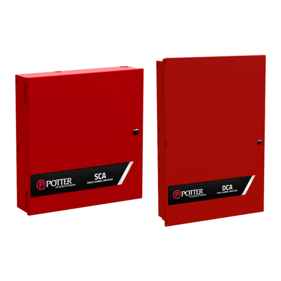
Summary of Contents for Potter DCA
- Page 1 SCA and DCA Single Channel and Dual Channel Amplifier Manual Potter Electric Signal Company, LLC St. Louis, MO Customer Service: (866) 240-1870 • Technical Support: (866) 956-1211 • Fax: (314) 595-6999 For listing information visit our website www.pottersignal.com Document 5409206-Rev. A...
- Page 2 SCA DCA INSTALLATION MANUAL-5409206-REV A 4/21 1. Installation Wiring Documents Figure 1. SCA-2525, SCA-2570, SCA-5025 and SCA-5070 Wiring Diagram Figure 2. SCA-10070 Wiring Diagram...
- Page 3 SCA DCA INSTALLATION MANUAL-5409206-REV A 4/21 Figure 3. DCA-5025 and DCA-10025 Type of Circuit Voltage Type Power Type AC Connection High Voltage Non-Power Limited Battery Connection Low Voltage Non-Power Limited P-Link Low Voltage Power Limited V-Link Low Voltage Power Limited...
-
Page 4: Main Supply Circuit
SCA DCA INSTALLATION MANUAL-5409206-REV A 4/21 Main Supply Circuit The AC terminal is located in the upper left hand portion of the main board. The main board supervises the main AC power and provides indication that the AC power is absent. - Page 5 P-Link The SCA and DCA amplifiers operate in conjunction as an expansion device with the IPA-4000V via P-Link. All expansion devices are supervised via the RS-485 connection. Wiring is fully supervised, and power limited. Any connection to ground of 0 ohms will be annunciated as a ground fault.
- Page 6 Figure 7. P-Link Class A Wiring Example V-Link The V-Link is a supervised proprietary bus that transmits audio to designated channels on SCA and DCA amplifiers. Wiring is fully supervised, and power limited. Any connection to ground of 0 ohms will be annunciated as a ground fault.
-
Page 7: Technical Specifications
SCA DCA INSTALLATION MANUAL-5409206-REV A 4/21 Figure 10. VM-1000 VLINK1 and 2 Class B Figure 11. VM-1000 VLINK1 and 2 Class A Technical Specifications SCA-2525, SCA-2570, SCA-5025 and SCA-5070 Standby Current 58 mA Alarm Current 608 mA Maximum number of amplifiers SCA Cabinet Dimensions 16”... -
Page 8: General Wiring Information
When the panel is installed, the National Electrical Code (NEC, NFPA 70) should be followed for the proper installation and separation of power limited and non-power limited circuits. The mixing of power limited, and non- power limited should be avoided. Refer to the following figure for suggested wiring routing. Figure 12. SCA and DCA Wire Routing... - Page 9 Figure 13. SCA and DCA Class A and Class B Speaker Wiring A maximum of thirty-one (31) SCA or DCA amplifiers can be utilized with an IPA-4000V which offers a total of 248 Class B or Class A speaker circuits. All speaker circuits are fully supervised and programmable through Potter...
- Page 10 SW-2 SW-3 SW-4 SW-5 The SCA and DCA amplifiers are equipped with a proprietary P-Link communication bus to operate in conjunction with an IPA-4000V. The amplifiers are also equipped with a proprietary V-Link bus to receive audio from the VM-...
- Page 11 SCA DCA INSTALLATION MANUAL-5409206-REV A 4/21 The 70V-1000 may be installed on the DCA-5025 and DCA-10025 to extend the voltage output to 70.7V. Refer to the 70V-1000 installation sheet (#5409211) for additional information including mounting. Figure 15. 70V-1000 The BUA-1000 may be installed on the DCA-5025 and DCA-10025 to provide backup amplification during internal amplifier failure.
- Page 12 SCA-2525, SCA-2570, SCA-5025, SCA-5070 and DCA-5025: A maximum of 50W per circuit at 25V and 70V. SCA-10070: A maximum of 100W on circuit 1 at 25V and 70V, and 50W maximum on circuits 2-8 at 25V and 70V DCA-10025: A maximum of 100W on circuits 1 and 5 at 25V and 70V, and maximum of 50W on circuits 2, 3, 4, 6, 7 and 8 at 25V and 70V.
- Page 13 SCA DCA INSTALLATION MANUAL-5409206-REV A 4/21 Appendix A: Battery Calculation Worksheets Total Total Standby Alarm Description Quantity Standby Alarm (mA) (mA) (mA) (mA) SCA-2525 Total (mA) Total (ma) Convert to Amps x 0.001 Convert to Amps x 0.001 (*Refer to maximum allowable standby current) Total A:...
- Page 14 SCA DCA INSTALLATION MANUAL-5409206-REV A 4/21 SCA-5070 Total (mA) Total (ma) Convert to Amps x 0.001 Convert to Amps x 0.001 (*Refer to maximum allowable standby current) Total A: Total A: 60 minutes per hour Alarm time (minutes) Multiply by standby hours x____ ÷...
- Page 15 SCA DCA INSTALLATION MANUAL-5409206-REV A 4/21 DCA-10025 BUA-1000 70V-1000 Total (mA) Total (ma) Convert to Amps x 0.001 Convert to Amps x 0.001 (*Refer to maximum allowable standby current) Total A: Total A: 60 minutes per hour Alarm time (minutes)


Need help?
Do you have a question about the DCA and is the answer not in the manual?
Questions and answers