Table of Contents
Advertisement
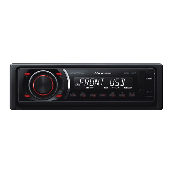
CD RECEIVER
DEH-3150UB
DEH-3150UB
DEH-3150UB
DEH-3190UB
DEH-3110UB
This service manual should be used together with the following manual(s):
Model No.
Order No.
CX-3240
CRT4050
For details, refer to "Important Check Points for Good Servicing".
PIONEER CORPORATION
PIONEER ELECTRONICS (USA) INC. P.O. Box 1760, Long Beach, CA 90801-1760, U.S.A.
PIONEER EUROPE NV Haven 1087, Keetberglaan 1, 9120 Melsele, Belgium
PIONEER ELECTRONICS ASIACENTRE PTE. LTD. 253 Alexandra Road, #04-01, Singapore 159936
PIONEER CORPORATION 2008
Mech.Module
S10.5COMP2-iPod/USB
CD Mech. Module : Circuit Descriptions, Mech. Descriptions, Disassembly
4-1, Meguro 1-chome, Meguro-ku, Tokyo 153-8654, Japan
DEH-3150UB/XN/ES
/XN/ES1
/XN/CN5
/XN/ID
/XN/UR
Remarks
ORDER NO.
CRT4236
/XN/ES
K-ZZZ. OCT. 2008 Printed in Japan
Advertisement
Table of Contents

Related Manuals for Pioneer DEH-3190UB


Summarization of Contents
Safety Information
Servicing Precautions
Manual intended for qualified technicians, not DIY.
Laser Safety Warning
Warning about invisible laser radiation and handling precautions.
Laser Diode Characteristics
Technical specifications of the laser diode.
Battery Replacement Caution
Warning regarding explosion risk during battery replacement.
Important Check Points for Good Servicing
Product Safety Practices
General safety practices for servicing, product regulations, and environment.
Adjustments
Procedures for optimum adjustments and characteristic confirmation.
Lubricants, Glues, and Replacement Parts
Guidelines for using lubricants, glues, and replacement parts.
Cleaning
Proper cleaning procedures for parts to restore performance.
Shipping Mode and Screws
Procedures for setting shipping mode or installing screws for transit.
Service Precautions
Service Precautions Details
Adhering to regulations and safety instructions during servicing.
Notes on Soldering
Guidelines and considerations for using lead-free solder.
Specifications
Product Specifications
Detailed technical specifications for various models.
Disc and Content Formats
Supported disc formats and content types for playback.
Panel Facilities Overview
Description of the functions and layout of the unit's front panel.
Connection Diagram
Visual guide for connecting the unit to power, speakers, and other components.
Device Element Descriptions
Head Unit Overview
Overview of the main unit's components and controls.
Remote Control Operation
Explanation of how the remote control operates.
Display Indication Overview
Display Indicators
Explanation of various indicators and their meanings on the display.
Front Panel Fastening
Front Panel Fastening
Instructions on how to fasten the front panel of the unit.
Basic Items for Service
Post-Servicing Check Points
Essential checks to perform after completing a service procedure.
PCB Locations
PCB Locations
Identification and location of key Printed Circuit Boards within the unit.
Jigs, Grease, and Cleaning
Jigs List
List of specialized jigs required for testing and calibration.
Grease List
List of greases used for mechanism lubrication and their specific applications.
Cleaning Procedures
Procedures for cleaning specific parts before product shipment.
Block Diagram
Tuner Amp Unit Block Diagram
Functional block diagram of the tuner amplifier section.
CD Core Unit Block Diagram
Functional block diagram of the CD core unit, including MP3/WMA decoding.
Diagnosis
Operational Flowchart
Flowchart illustrating the power-on sequence and initial checks of the unit.
Error Code List
Error Code List
Table of error codes, their displayed messages, and potential causes.
Connector Function Description
Connector Function Description
Description of the functions of various connectors on the rear and front of the unit.
Service Mode
Display Test Mode
Instructions for entering and operating the display test mode.
CD Test Mode
CD Test Mode Flow Chart
Flowchart detailing the steps and operations within the CD test mode.
Disassembly
Removing the Case
Procedure for removing the main case of the unit.
CD Mechanism Module Removal
Step-by-step guide for removing the CD mechanism module.
Tuner Amp Unit Removal
Step-by-step guide for removing the tuner amplifier unit.
Front Panel Cap Handling
Removing the Front Panel Cap
Instructions for removing and attaching the front panel cap.
Mechanism Unit Handling
Holding the Mechanism Unit
Guidance on how to properly hold the mechanism unit during handling.
Upper and Lower Frames Removal
Procedure for disassembling the upper and lower frames of the mechanism.
CD Mechanism Component Removal
CD Core Unit Removal
Steps to safely remove the CD core unit from the mechanism.
Pickup Unit Removal
Detailed procedure for removing the pickup unit from the CD mechanism.
Setting and Adjustment
CD Adjustment Cautions
Important cautions and considerations before performing CD mechanism adjustments.
CD Test Mode Operation
Instructions for entering and using the test mode for CD mechanism adjustment.
Pickup Unit Grating Check
PU Unit Replacement Note
Note that PU unit replacement is a last resort and grating needs checking.
Grating Check Purpose
Objective of checking the grating angle after changing the PU unit.
Mal-adjustment Symptoms
Potential issues arising from incorrect grating angle.
Grating Check Method
Required equipment, points, disc, and mode for grating check.
Grating Check Procedure
Step-by-step procedure for checking the grating angle using test mode.
Exploded Views and Parts List
Packing Exploded View
Exploded view of the packing configuration and associated parts list.
Exterior Views and Parts List
Exterior View (1)
Exploded view showing exterior parts of the unit (Part 1).
Exterior Views and Parts List
Exterior View (2)
Exploded view showing exterior parts of the unit (Part 2).
CD Mechanism Module
CD Mechanism Module Exploded View
Exploded view of the CD mechanism module components.
Schematic Diagram
Tuner Amp Unit Schematic
Circuit diagram for the tuner amplifier unit.
Keyboard Unit
Keyboard Unit Schematic
Circuit diagram for the keyboard unit, showing button connections and IC layout.
PCB Connection Diagram
Panel Unit PCB Connections
Diagram showing PCB connections for the panel unit to the mother board.
CD Mechanism Module Guide Page
Pickup Unit Overview
Overview of the pickup unit and its service points.
Switches and Motor Driver Logic
Description of switches and motor driver logic table for the CD mechanism.
CD Core Unit Block Diagram
CD Core Unit Block Diagrams
Functional block diagrams of the CD core unit.
Waveforms
CD Core Unit Waveforms
Oscilloscope waveforms for various signals within the CD core unit.
PCB Connection Diagram
Tuner Amp Unit PCB Connections
Diagram showing PCB component layout and connections for the tuner amp unit.
Keyboard Unit PCB Connection
Keyboard Unit PCB Side A
PCB component layout and connections for the keyboard unit, Side A.
Keyboard Unit PCB Connection
Keyboard Unit PCB Side B
PCB component layout and connections for the keyboard unit, Side B.
CD Core Unit PCB Connection
CD Core Unit PCB Side A
PCB component layout and connections for the CD core unit, Side A.
CD Core Unit PCB Connection
CD Core Unit PCB Side B
PCB component layout and connections for the CD core unit, Side B.
Panel Unit PCB Connection
Panel Unit PCB Side A
PCB component layout and connections for the panel unit, Side A.
Panel Unit PCB Side B
PCB component layout and connections for the panel unit, Side B.
Electrical Parts List
Miscellaneous Electrical Parts
List of miscellaneous electrical components and their part numbers.
Need help?
Do you have a question about the DEH-3190UB and is the answer not in the manual?
Questions and answers