Advertisement
Quick Links
Advertisement

Related Manuals for Lennox GCS16H-311-75


Summarization of Contents
I. APPLICATION
GCS16 2-5 ton units
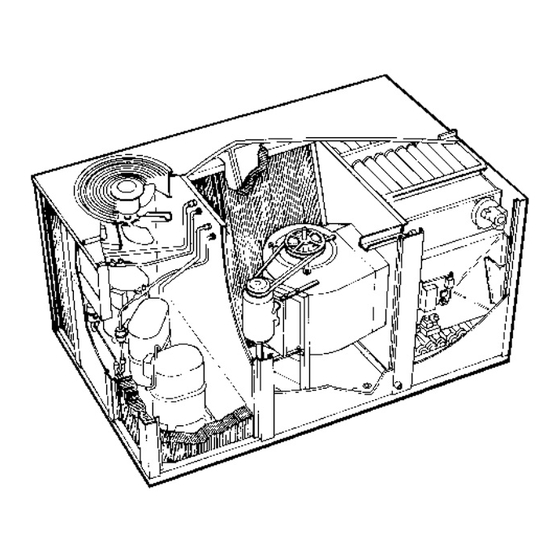
Overview of GCS16 units available in three models and three cabinet sizes.
II. UNIT COMPONENTS
A-Control Box Components
Description of the control box, its location, and access for GCS16H and GCS16.
1-Terminal Strip TB1
Describes Terminal Strip TB1 for indoor thermostat and outdoor unit low voltage control wiring.
2-Transformer T1
Describes Transformer T1 used in GCS16 series units for 24VAC to control circuits.
3-Transformer Fuse F1
Details Transformer Fuse F1 for 460/575 volt units, providing overcurrent protection.
4-Transformer T3
Describes Transformer T3 used in 460/575 volt units for combustion air blower.
5-Transformer T4
Details Transformer T4 for 460 volt units, powering the indoor blower.
6-Cooling Contactor K1
Explains Cooling Contactor K1, its function with the thermostat and compressor.
7-Indoor Blower Relay K20 (Cooling Speed)
Describes Indoor Blower Relay K20 for cooling speed control.
8-Potential Relay K31
Explains Potential Relay K31 used in higher-end units to control compressor operation.
9-Combustion Air Blower Relay K13
Describes Combustion Air Blower Relay K13, controlling combustion air blower operation.
10-Indoor Blower Relay K20 (Heating Speed)
Details Indoor Blower Relay K20 for heating speed control.
IV. ELECTRICAL CONNECTIONS
A-Power Supply
Details power supply requirements, including voltage and wiring connections.
V. REFRIGERATION SYSTEM SERVICE CHECKS
A-Gauge Manifold Attachment
Details connecting gauge manifolds for pressure checks.
B-Charging
Outlines procedures for charging the unit with refrigerant, including temperature checks.
VII. HEATING SYSTEM SERVICE CHECKS
A. G.A./C.G.A. Applications and Requirements
Refers to manual for A.G.A. and C.G.A. applications and requirements.
B-Gas Piping
Provides guidelines for gas supply piping installation and safety.
C-Testing Gas Piping
Explains manual gas shut-off valve operation for safety during testing.
D-Testing Gas Supply Pressure
Details testing gas supply pressure at the field (field provided).
E-Check and Adjust Manifold Pressure
Explains how to check and adjust manifold pressure using the gas valve.
F-Proper Gas Flow
Describes how to check gas flow and calculate CFM per hour.
VIII. INDOOR BLOWER OPERATION / ADJUSTMENT
A-Blower Operation
Describes blower operation modes based on thermostat settings.
B-Determining Unit CFM
Explains how to measure static pressure and air filters for CFM determination.
D-Blower Speed Adjustment 460V and 575V Units Only
Details how to adjust blower speed using pigtails on 460V/575V units.
B-Filters
Discusses field-provided filters, installation, and maintenance.
C-Heat Exchanger
Guides on checking and cleaning the heat exchanger and checking gaskets.
D-Burner
Details periodic inspection and cleaning of the burner assembly.
E-Combustion Air Blower
Describes inspection and cleaning procedures for the combustion air blower.
XI. ACCESSORIES
A-Lifting Lug Kit
Describes optional lifting lug kits for unit installation.
B-RMF16 Mounting Frame
Details the RMF16 roof mounting frame for downflow discharge.
C-Economizers
Introduces economizer types and their applications with GCS16 units.
2-REMD16 Downflow Economizer
Describes the REMD16 downflow economizer and its damper operation.
3-EMDH16 Horizontal Economizer
Details the EMDH16 horizontal economizer and its damper operation.
4-Economizer Operation
Explains economizer operation modes: setpoint control, minimum positioner, enthalpy sensor.
h-Warm Up Kit
Describes the warm-up kit for enhancing heating performance.
i-Night Relay
Details the night relay for reducing energy consumption.
E-RDE16 Duct Enclosure for REMD16-41 and REMD16M-41 Economizer Limited Application GCS16 Series Units Only
Explains the RDE16 duct enclosure for economizer installation.
F-LPG Gas Kit
Describes the LPG gas kit for converting Natural Gas units to LPG.
G-Condenser Coil Guard Kit
Details the optional condenser coil guard kit for unit protection.
H-High Altitude Kit (CGA only)
Mentions the high altitude kit is not available at this time.
I-Compressor Crankcase Heater
Describes the optional crankcase heater for field installation.
J-DF16 Downflow Filter Kit
Details the optional DF16 downflow filter kit for economizer operation.
K-Timed-Off Control Kit (Figure 68)
Explains the timed-off control kit to prevent compressor short cycling.
L-Optional Compressor Monitor (Figure 69)
Describes the optional compressor monitor for low ambient protection.
M-Low Ambient Kit
Details the optional low ambient kit for outdoor operation.
N-Roof Curb Power Kit
Describes the roof curb power kit for mounting.
O-Firestats
Explains firestat wiring and controls for safety.
P-Transitions
Describes optional supply/return transitions for economizer mounting.
Q-Supply and Return Diffusers
Details optional flush mount diffusers and return air diffusers.
R-Status Panels SP11 and SP11
Describes status panels for system monitoring.
4-Installation and Wiring
Guides on installing and wiring control kits and status panels.
XII. WIRING DIAGRAMS AND OPERATION SEQUENCE
Installation of Plug-In Kits
Details the installation of plug-in kits for economizer control.
D-Warm-up Kit
Explains warm-up kit operation with different control systems.
E-W973 Control System
Describes the W973 control system for programmable operation.
Need help?
Do you have a question about the GCS16H-311-75 and is the answer not in the manual?
Questions and answers