Advertisement
Quick Links
Service Literature
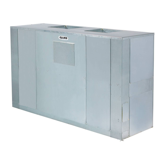
Lennox TAA model blower−coil units are designed for up
flow or horizontal air and indoor applications only. TAA
blower units are available in six models; 072, 090, 120,
150, 180 and 240. The units match up with Lennox TSA
condensing units and Lennox TPA heat pump units
charged with HFC−410A refrigerant.
Information and specifications contained in this manual
are subject to change. Procedures outlined in this manual
are presented as a recommendation only and do not su-
persede or replace local or state codes.
WARNING
Improper installation, adjustment, alteration, service or
maintenance can cause personal injury, loss of life, or
damage to property.
Installation and service must be performed by a licensed
professional installer (or equivalent) or a service agency.
WARNING
Electric shock hazard. Can cause in-
jury or death. Before attempting to
perform any service or maintenance,
turn the electrical power to unit OFF
at disconnect switch(es). Unit may
have multiple power supplies.
Corp. 0905−L2
Revised March 13, 2012
TAA SERIES UNITS
Specifications
Options / Accessories
Blower Data
Electric Heat Data
I Unit Components
II Refrigeration System
III Blower Speed and Belt Adjustment
IV Electric Heat
V Diagrams
Page 1
TABLE of CONTENTS
. . . . . . . . . . . . . . . . . . . . . . .
. . . . . . . . . . . . . . . .
. . . . . . . . . . . . . . . . . . . . . . . . .
. . . . . . . . . . . . . . . . . . .
. . . . . . . . . . . . . . . . . . .
. . . . . . . . . . . . . . .
. . . . . . . . . . . . . . . . . . . . . .
. . . . . . . . . . . . . . . . . . . . . . . . .
TAA
Page 2
Page 4
Page 5
Page 15
Page 21
Page 22
. .
Page 22
Page 23
Page 24
2012 Lennox Industries Inc.
Litho U.S.A.
Advertisement

Subscribe to Our Youtube Channel
Related Manuals for Lennox TAA Series


Summary of Contents for Lennox TAA Series
- Page 1 TAA blower units are available in six models; 072, 090, 120, 150, 180 and 240. The units match up with Lennox TSA condensing units and Lennox TPA heat pump units charged with HFC−410A refrigerant.
-
Page 2: Specifications
SPECIFICATIONS General Model No. TAA072S4S TAA090S4D Data Nominal Tonnage Liquid line o.d. − in. (sweat) Connections (1) 5/8 (2) 5/8 Suction/Vapor line o.d. − in. (sweat) (1) 1−1/8 (2) 7/8 Condensate drain − in. (fpt) 1 (NPT) 1 (NPT) Refrigerant Not Furnished R−410A R−410A... -
Page 3: Options & Accessories
OPTIONS / ACCESSORIES Catalog Item BLOWER Blower Drives See Blower Drive Specifications Table on Page 12 CABINET Corrosion Protection Factory Float Switch T2SNSR71LN1− 91W69 T2GARD30L−1 47W49 Return Air Grille T2GARD30M−1 47W50 T2GARD30N−1 47W51 CONTROLS ® L Connection Network See separate bulletin MSAV KIT VOLTAGE/ MOTOR SIZE... - Page 4 OPTIONS / ACCESSORIES (continued) Item Catalog ELECTRIC HEAT 10 kW 208/240V−3ph − T3EH0010LM1Y 46W50 460V−3ph − T3EH0010LM1G 46W55 575V−3ph − T3EH0010LM1J 46W60 15 kW 208/240V− 3ph − T3EH0015LM1Y 46W51 460V−3ph − T3EH0015LM1G 46W56 575V−3ph − T3EH0015LM1J 46W61 25 kW 208/240V−3ph − T3EH0025LM1Y 46W52 460V−3ph −...
-
Page 5: Blower Data
BLOWER DATA TAA072 BLOWER PERFORMANCE All data is measured external to the unit with dry coil and standard 2 in. air filters in place. FOR ALL UNITS ADD: 1 − Wet indoor coil air resistance of selected unit. 2 − Any field installed accessories air resistance (electric heat, economizer, etc.) See page 13. Then determine from table the blower motor hp and drive rpm required. - Page 6 TAA090 BLOWER PERFORMANCE All data is measured external to the unit with dry coil and standard 2 in. air filters in place. FOR ALL UNITS ADD: 1 − Wet indoor coil air resistance of selected unit. 2 − Any field installed accessories air resistance (electric heat, economizer, etc.) See page 13. Then determine from table the blower motor hp and drive rpm required.
- Page 7 TAA120 BLOWER PERFORMANCE All data is measured external to the unit with dry coil and standard 2 in. air filters in place. FOR ALL UNITS ADD: 1 − Wet indoor coil air resistance of selected unit. 2 − Any field installed accessories air resistance (electric heat, economizer, etc.) See page 13. Then determine from table the blower motor hp and drive rpm required.
- Page 8 TAA150 BLOWER PERFORMANCE All data is measured external to the unit with dry coil and standard 2 in. air filters in place. FOR ALL UNITS ADD: 1 − Wet indoor coil air resistance of selected unit. 2 − Any field installed accessories air resistance (electric heat, economizer, etc.) See page 13. Then determine from table the blower motor hp and drive rpm required.
- Page 9 TAA180 BLOWER PERFORMANCE All data is measured external to the unit with dry coil and standard 2 in. air filters in place. FOR ALL UNITS ADD: 1 − Wet indoor coil air resistance of selected unit. 2 − Any field installed accessories air resistance (electric heat, economizer, etc.) See page 14. Then determine from table the blower motor hp and drive rpm required.
- Page 10 TAA240 BLOWER PERFORMANCE All data is measured external to the unit with dry coil and standard 2 in. air filters in place. FOR ALL UNITS ADD: 1 − Wet indoor coil air resistance of selected unit. 2 − Any field installed accessories air resistance (electric heat, economizer, etc.) See page 14. Then determine from table the blower motor hp and drive rpm required.
- Page 11 STATIC PRESSURE EXTERNAL TO UNIT − Inches Water Gauge Volume 4400 2.44 2.61 2.78 2.93 3.09 3.24 1017 3.40 4600 2.55 2.73 2.90 3.06 3.21 3.37 1022 3.53 4800 2.66 2.85 3.02 3.18 3.34 3.50 1028 3.66 5000 2.79 2.97 3.14 3.31 3.48...
- Page 12 NOTE − Using total air volume and system static pressure requirements, determine from blower performance tables rpm and motor horsepower required. Maximum usable horsepower of motors furnished by Lennox are shown. In Canada, nominal motor horsepower is also maximum usable motor horsepower.
- Page 13 TAA072−090 ACCESSORY AIR RESISTANCE TAA072 TAA090 ID AIR Electric Hot Water Wet Coil Wet Coil MERV 10 MERV15 Economizer heat Coil Drop Drop 1600 0.05 0.07 0.02 0.04 0.02 0.00 0.08 1700 0.06 0.08 0.02 0.04 0.03 0.00 0.09 1800 0.06 0.09 0.02...
- Page 14 TAA180−240 ACCESSORY AIR RESISTANCE TAA180 TAA240 Electric Hot Water ID AIR Wet Coil Wet Coil MERV 10 MERV15 Economizer heat Coil Drop Drop 3250 0.07 0.06 0.01 0.04 0.02 0.04 0.16 3500 0.07 0.07 0.01 0.04 0.02 0.05 0.18 3750 0.08 0.08 0.01...
- Page 15 TAA072 OPTIONAL ELECTRIC HEAT DATA Total Unit + Electric Heat Total Unit + Electric Heat Minimum Circuit Maximum Overcurrent Electric Heat Volts Btuh Ampacity Protection Size Input Input Output Steps 1.5 hp 2 hp 1.5 hp 2 hp 10 kW 25,600 28,700 31,400...
- Page 16 TAA090 OPTIONAL ELECTRIC HEAT DATA Total Unit + Electric Heat Total Unit + Electric Heat Minimum Circuit Maximum Overcurrent Electric Heat Volts Btuh Ampacity Protection Size Input Input Output Steps 2 hp 3 hp 2 hp 3 hp 10 kW 25,600 28,700 31,400...
- Page 17 TAA120 OPTIONAL ELECTRIC HEAT DATA Total Unit + Electric Heat Total Unit + Electric Heat Minimum Circuit Maximum Overcurrent Electric Heat Volts Btuh Ampacity Protection Size Input Input Output Steps 2 hp 3 hp 2 hp 3 hp 10 kW 25,600 28,700 31,400...
- Page 18 TAA150 OPTIONAL ELECTRIC HEAT DATA Total Unit + Electric Heat Total Unit + Electric Heat Minimum Circuit Maximum Overcurrent Electric Heat Volts Btuh Ampacity Protection Size Input Input Output Steps 3 hp 5 hp 3 hp 5 hp 10 kW 25,600 28,700 31,400...
- Page 19 TAA180 OPTIONAL ELECTRIC HEAT DATA Total Unit + Electric Heat Total Unit + Electric Heat Minimum Circuit Maximum Overcurrent Electric Heat Volts Btuh Ampacity Protection Size Input Input Output Steps 3 hp 5 hp 3 hp 5 hp 20 kW 14.8 50,600 16.5...
- Page 20 TAA240 OPTIONAL ELECTRIC HEAT DATA Total Unit + Electric Heat Total Unit + Electric Heat Minimum Circuit Maximum Overcurrent Electric Heat Volts Btuh Ampacity Protection Size Input Input Output Steps 5 hp 7.5 hp 5 hp 7.5 hp 20 kW 14.8 50,600 16.5...
-
Page 21: I − Unit Components
I − UNIT COMPONENTS ciency motors only. S42 is connected in line with the blower motor to monitor the current flow to the motor. When the A − Blower Contactor K3 relay senses an overload condition, a set of N.C. contacts open to de−energize all 24 volt circuits. -
Page 22: Refrigeration System
II − REFRIGERATION SYSTEM Units are equipped with single refrigerant circuit (072) or dual refrigerant circuit (090−240). The 090−240 units have a dual distribution system for two stage capacity control during cooling cycles. Each circuit has its own service valve connection and expansion valve. - Page 23 IV − Electric Heat Components See electric heat tables (table of contents) for electric heat 5 − Fuse F3 matchups. EHA units consists of electric heating elements Heating elements in all T3EHA units are protected by fuse exposed to the air stream. Multiple−stage elements are se- F3.
- Page 24 V − Wiring Diagrams TAA072/240 − SEQUENCE OF OPERATION 1. W1 heat demand energizes the economizer relay K43. 3. K3−1 closes energizing indoor blower B3. 2. When K43−1 closes blower relay K3 is energized. Page 24...
- Page 25 T3EH 072/150, 10−15 kW Y Voltage − Sequence of Operation Heat Call TSA / TPA 3. K15−1 closes and assuming primary limit S15 and secon- dary limit S20 are closed, heating elements HE1 and HE2 1. W1 (W2 in TPA) heat demand energizes the econo- are energized.
- Page 26 T3EH 072/150, 25−35 kW Y Voltage − Sequence of Operation First Stage Heat Call 3. K15−1 closes and assuming primary limit S15 and secon- dary limit S20 are closed, heating elements HE1 and HE2 are energized. 1. TSA − W1 heat demand energizes the economizer Second Stage Heat Call TSA / TPA relay K43 and heat relay K9.
- Page 27 T3EH 072/150, 10−35 kW G, J, M Voltage − Sequence of Operation Heat Call TSA / TPA 3. K15−1 closes and assuming primary limit S15 and secon- dary limit S20 are closed, heating elements HE1 and HE2 1. W1 (W2 in TPA) heat demand energizes the econo- are energized.
Need help?
Do you have a question about the TAA Series and is the answer not in the manual?
Questions and answers