
Related Manuals for ROTORCOMP EVO42


Summarization of Contents
Foreword
1.1 General
Information and regulations for installation and operation of screw compressor air ends.
1.2 Scope
Applicability of documentation for specific screw compressor air end models from delivery date.
1.3 Change service
Statement that the document is not subject to change service.
1.4 Abbreviations
List of abbreviations used in the operating manual.
1.5 Manufacturer's information
General information about the manufacturer and the operating manual's purpose.
1.6 Warranty information, liability disclaimer
Conditions of warranty and limitations of liability for the compressor components.
1.7 Nameplates
Information on the location and importance of nameplates on the unit.
Safety Precautions
2.1 Marking of safety precautions
Explanation of safety symbols (Warning, Caution, Note) and their meanings.
2.2 Safety regulations
National and international safety regulations for pressure vessels and operation.
2.3 General safety precautions
Important instructions for installation, commissioning, operation, and maintenance.
2.3.1 Special symbols
Visual representation of various safety warnings and their meanings.
2.3.2 Information on use of safety equipment
Guidance on wearing appropriate personal safety equipment.
Technical Description
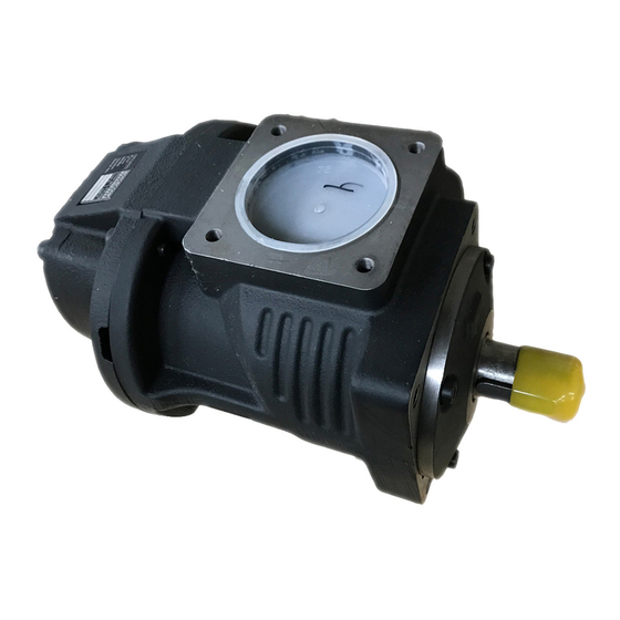
3.1 General overview of screw compressor air ends
Description and diagram of screw compressor air ends (EVO2 to EVO42-G).
Transport
4.1 Delivery and packing
Information on product delivery, packaging, and checking the scope.
4.2 Transport damage
Procedures for checking and reporting transport damage.
4.3 Transporting unpacked system
Guidelines for safely moving the compressor air end using lifting equipment.
Installation
5.1 Assembly
Steps and precautions for assembling the screw compressor air end.
5.1.1 Fastening screws
Details on using standard fastening screws for mounting.
5.1.2 Three-point fastening
Alternative fastening method using three mounting points.
5.1.3 Pipe connections
Guidelines for connecting pipes, avoiding conical threads.
5.2 Safety precautions for installation and assembly
Essential safety measures during installation and assembly processes.
5.3 Installation information
General advice for installing the compressor air end, including location and alignment.
5.3.1 Drive
Information on connecting drive mechanisms and shaft rotation.
5.4 Belt drive
Details on proper design and installation of V-belt drives.
5.4.1 Belt tensioner with scale
Instructions for using and adjusting the belt tensioner with a scale.
5.5 Direct drive
Considerations for direct drive installation and using elastic couplings.
5.5.1 Dimensions of centering flange
Specifications for centering flange dimensions for direct drive units.
5.6 Air inlet
Requirements for air filtration and inlet air quality.
5.7 Air outlet
Guidelines for air outlet connections, pressure loss, and safety valve.
5.8 Oil cooling
Requirements and considerations for the design of oil cooling systems.
5.9 Service
Ensuring accessibility for essential maintenance and service points.
Commissioning
6.1 Preparation for commissioning
Steps and checks required before initial start-up of the system.
6.2 Checking direction of rotation
Procedure to verify the correct rotation direction of the compressor air end.
6.3 Test run
Steps and safety precautions during the initial test run.
6.4 Recommissioning screw compressor air end system
Procedures for restarting the system after extended shutdown.
Maintenance
7.1 Safety precautions
Safety guidelines for all maintenance, assembly, and repair work.
7.2 Oil level
Importance and procedure for checking the oil level in the oil reservoir.
7.2.1 Oil level check via oil filler opening
Detailed steps for checking the oil level through the filler opening.
7.3 Oil change
Procedures and safety measures for performing an oil change.
7.3.2 Oil drain point
Location and procedure for draining used oil from the system.
7.3.3 Filling with oil
Steps for refilling oil after an oil change.
7.4 Maintenance check sheet
Template for recording performed maintenance activities and measurements.
7.5 Maintenance intervals
Recommended maintenance schedules and tasks based on operating hours.
Lubricants and Operating Materials Maintenance Parts
8.1 Lubricants and operating materials
General information on lubricants and operating materials for compressor air ends.
8.1.1 Oil recommendation
Guidance on suitable oils and manufacturers for compressor air ends.
8.1.2 Topping up oil
Procedure for topping up oil, using the same brand and type.
8.1.3 Measures at low room temperature
Precautions for operating the system in cold environments.
8.1.4 Piping materials
Considerations for plastic compressed-air piping materials attacked by oil.
8.1.5 Pressure dew point of compressed air
Factors affecting compressed air pressure dew point with examples.
8.1.6 Temperatures
Optimal operating temperatures and thermal economy considerations.
8.1.7 Condensate damage
Preventing condensate formation by considering humidity and pressure.
8.1.8 Cold starts
Considerations for oil viscosity and drive load during cold starts.
8.1.9 Oil separation
How oil separation performance is affected by outlet temperature.
8.1.10 Multigrade oil
Reasons why multigrade oils are not approved for use in these units.
Technical Data and Tightening Torques
9.1 Technical data
Table of technical specifications for various screw compressor air end models.
9.2 Tightening torques
Recommended torque values for different screw/bolt types and threads.
Need help?
Do you have a question about the EVO42 and is the answer not in the manual?
Questions and answers