
Related Manuals for ROTORCOMP EVO9


Summarization of Contents
Foreword
General Information
Information and regulations for installation and operation of screw compressor air ends.
Scope of Documentation
Applicability of the manual to specific screw compressor air end models and from delivery date.
Change Service
Indicates that the document is not subject to the change service.
Abbreviations
Lists common abbreviations used in the manual, such as bar (g), Bh, DHV, RC, SIV.
Manufacturer's Information
Provides information on operating principles, installation, operation, and maintenance of the screw compressor air ends.
Purpose of Use
Details the intended use of screw compressor air ends and conditions for operation with gases or other media.
Delivery Scope
Specifies that ROTORCOMP supplies screw compressor air ends in accordance with the order confirmation.
Optional Components
Information on matching components offered by ROTORCOMP for system construction and application.
Warranty and Liability
Outlines ROTORCOMP's responsibilities, voiding conditions, and liability disclaimers for component defects.
Nameplates
Explains the location and importance of nameplates for identification and correspondence.
Safety Precautions
Safety Precaution Markings
Explains symbols (Warning, Caution, Note) used to highlight hazards, technical safety, and operational safety.
Safety Regulations
Highlights the need to observe country-specific regulations for pressure vessels and operating safety ordinances.
General Safety Precautions
Emphasizes observing all instructions, reading the manual, and potential hazards from non-compliance.
Special Symbols
Illustrates and explains various symbols indicating danger points, hazards, and specific operational warnings.
Safety Equipment Usage
Provides guidance on using safety helmets, shoes, and personal protective equipment as per local regulations.
Technical Description
Overview of Screw Compressor Air Ends
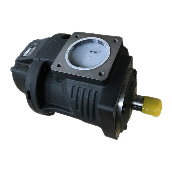
Presents a general overview with diagrams and labels for the EVO screw compressor air ends models.
Transport
Delivery and Packing
Describes how the system is delivered in suitable packing according to shipping method and conditions.
Transport Damage
Advises checking for damage during transport and procedures for claims and notifications.
Transporting Unpacked Systems
Details safe methods for moving screw compressor air ends using cranes or lift trucks, with safety warnings.
Installation
Assembly and Connections
Covers fastening screws, three-point fastening, and pipe connections for compressor air ends, including thread types and torque.
Installation and Assembly Safety
Provides safety instructions for lifting, handling, air intake, and grounding of screw compressor air ends.
Installation Information and Drive
Details optimal installation location, alignment, operating angles, and drive considerations for screw compressor air ends.
Belt Drive Installation
Guidelines for proper design and installation of V-belt drives to ensure bearing life and shaft integrity.
Direct Drive Installation
Information on direct drive installation, elastic couplings, and centering flange dimensions.
Air Inlet and Quality
Specifies requirements for air filtration and inlet air quality according to ISO 8573 standards.
Air Outlet
Recommendations for minimizing pressure loss, connecting outlet pipes stress-free, and safety regarding safety valves.
Oil Cooling System
Details on oil cooling system design, temperature limits, and installation for optimal performance.
Service Accessibility
Ensures good accessibility to service points like oil filling, drain, filter replacement, and shaft seal replacement.
Commissioning
Preparation for Commissioning
Checks to be performed before initial start-up, including installation, oil addition, and safety regulations.
Checking Direction of Rotation
Procedure to check the correct direction of rotation for standard and transmission models to prevent damage.
Test Run Procedures
Guidelines for conducting a test run, including safety measures like closing the shut-off valve and using a reservoir.
Recommissioning
Measures required for recommissioning systems that have been shut down or stored for over three months.
Maintenance
Maintenance Safety Precautions
Ensures maintenance is done by qualified personnel, using correct tools, genuine parts, and with power off.
Oil Level Check
Importance of checking oil level before commissioning and every 100 operating hours for operating safety.
Checking Oil Level via Filler Opening
Step-by-step procedure for checking the oil level through the filler opening, including safety warnings.
Oil Change Intervals
Specifies intervals for oil changes based on system manufacturer and operating parameters.
Oil Change Procedures
Details on performing oil changes, including drain points, and filling with new oil.
Oil Drain Point
Describes the location and procedure for draining used oil from the system.
Filling with Oil
Instructions for refilling the system with oil after an oil change, including recommendations and checks.
Maintenance Check Sheet
Provides a template for recording maintenance tasks performed, including dates and mechanic details.
Maintenance Intervals
Outlines recommended maintenance intervals and corresponding tasks for screw compressor modules.
Lubricants and Operating Materials
Lubricants, Oils, and Materials
Covers oil recommendations, topping up, low temperature measures, piping materials, and cooling oil requirements.
Compressed Air Pressure Dew Point
Explains how to determine the pressure dew point using a graph based on intake air temperature and humidity.
Operating Temperatures
Discusses optimal operating temperatures and the importance of thermal economy in the system design.
Condensate Damage Prevention
Highlights the importance of considering relative humidity and final operating pressures to prevent condensate formation.
Cold Starts
Addresses challenges during cold starts, focusing on oil viscosity and its impact on lubrication and drive load.
Oil Separation
Discusses the effect of outlet temperature on fine oil separation efficiency.
Multigrade Oil Warning
Warns against the use of multigrade oils due to potential long-term issues with viscosity improvers.
Technical Data and Tightening Torques
Technical Data
Presents technical specifications for various EVO screw compressor air end models, including drive outputs, volume flow, pressure, and weight.
Tightening Torques
Lists recommended maximum tightening torques for various screw/bolt types and threads, emphasizing the use of torque wrenches.
Troubleshooting
Incorrect Direction of Rotation
Identifies reversed phases as the cause and reconnecting supply lines as the remedy.
System Start-Up Issues
Lists possible causes like no electricity, high temperature cut-offs, or system flooding, with remedies.
Difficult System Start-Up
Covers issues like insufficient motor output, incorrect drive ratio, or system flooding, with checks and remedies.
Differential Pressure Issues
Addresses problems with viscous oil or high pressure in the separator cartridge, suggesting viscosity checks and cartridge replacement.
High Temperature Cut-Offs
Discusses causes like oil shortage, soiled filters, or defective thermostats, with corresponding remedies.
Safety Valve Issues
Covers scenarios where the safety valve blows off due to defects or continuous operation, with remedies.
Oil in Compressed Air
Addresses oil in compressed air caused by soiled extraction lines or defective separator cartridges, with remedies.
Discharge and Auto-Off Failures
Covers issues with network pressure monitor settings or solenoid/relief valve defects causing continuous discharge or failure to switch off.
Continuous Discharge and Low Feed
Relates to solenoid/relief valve defects or minimum pressure valve issues causing continuous discharge and low feed quantity.
Insufficient Feed Quantity
Addresses causes like soiled intake filters, oil shortage, or intake control valve issues, with remedies.
Control Valve Closing Issues
Covers control valve setting issues or damaged sealing surfaces, with remedies for checking and replacing parts.
Oil Exit During Stop
Addresses oil exiting through the intake control valve during stop due to damaged sealing or broken springs.
System Relief Failures
Covers solenoid valve/electrical system issues or impulse-pressure relief valve defects causing the system not to relieve.
Control Valve Constant Discharge
Relates to solenoid valve/electrical system issues causing the control valve to discharge constantly.
Oil Escape and Foam
Addresses issues with incorrect oil type or oil level leading to foam formation or escape during discharging.
Need help?
Do you have a question about the EVO9 and is the answer not in the manual?
Questions and answers