
Related Manuals for GESTRA ORGS 11-2


Summarization of Contents
Important Notes
Usage for the Intended Purpose
Specifies the intended use of the oil detector & alarm for cooling water systems.
Functional Overview
Explains how the oil detector & alarm operates based on conductivity.
Critical Safety Precautions
Highlights essential safety measures for installation and operation.
Directives and Standards
Marine Application Approvals
Confirms the equipment's approval for marine applications.
Regulatory Compliance (LV, EMC, ATEX)
Details compliance with Low Voltage, EMC, and ATEX directives.
Declaration of Conformity Information
Provides guidance on obtaining conformity and manufacturer declarations.
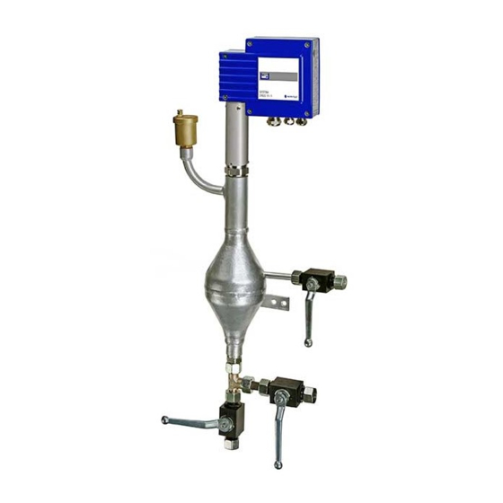
Product Design Overview
Describes the ORGS 11-2 and ORGS 11-1 components.
Technical Data
ORGS 11-2 Unit Specifications
Lists technical data for the ORGS 11-2 equipment unit.
ORGS 11-1 Electrode Specifications
Details technical data for the ORGS 11-1 measuring electrode.
Control Circuit Outputs
Specifies the volt-free change-over contacts and their ratings.
Indicators and Adjusters
Describes LEDs and the code switch for response sensitivity.
Electrical Connection Details
Outlines requirements for cable glands and terminal strips.
Protection Rating
States the IP protection rating (IP 65).
Ambient Temperature Limits
Specifies maximum admissible ambient and storage temperatures.
Certification Details
Lists marine certification bodies like DNV, GL, BV, LR.
Scope of Supply
Lists the items included in the product delivery package.
Name Plate and Marking
Safety Note for Name Plate
Advises on safety when referencing the nameplate.
Equipment Identification Markings
Explains designations, ratings, and material numbers on the plate.
Operational Limit Markings
Details pressure, temperature, and power rating information.
Compliance and Approval Markings
Covers CE marking and type approval numbers.
Manufacturer and Disposal Information
Identifies manufacturer details and disposal notes.
Installation
Installation Requirements
Outlines necessary conditions for proper installation of the unit.
Installation Examples
Presents diagrams illustrating typical installation scenarios.
ORGS 11-1 Dimensions
Provides detailed dimensions for the ORGS 11-1 electrode assembly.
ORGS 11-1 Diagram Key
Explains numbering in the ORGS 11-1 installation diagram.
ORGS 11-2 Dimensions
Displays comprehensive dimensions for the ORGS 11-2 unit.
ORGS 11-2 Installation Steps
Details the step-by-step procedure for installing the ORGS 11-2.
Required Installation Tools
Lists the tools needed for the installation process.
ORGS 11-2 Diagram Key
Explains numbering in the ORGS 11-2 installation diagram.
Electrical Connection
ORGS 11-1 Connection Diagram
Shows the overall electrical connection layout for the ORGS 11-1.
Measuring Electrode Connection
Details how to connect the ORGS 11-1 measuring electrode part.
ORGS 11-1 Unit Connection Procedure
Provides step-by-step instructions for connecting the ORGS 11-1 unit.
Electrical Connection Component Key
Explains the numbering of components in electrical diagrams.
Tools for Electrical Work
Lists the tools required for making electrical connections.
ORGS 11-1 Wiring Diagram
Presents the detailed wiring diagram for the ORGS 11-1.
Connecting with Various Supply Voltages
Explains connecting the unit with 24/115/230 V AC supply.
Basic Settings
Default Factory Settings
States the default factory values for the device.
Selecting Measuring Range
Guides on setting the measuring range using the code switch.
Commissioning Procedure
Applying Supply Voltage
Instructs on safely applying power to the unit.
Operating Valves
Details the procedure for operating the unit's integrated valves.
Normal Operation and Oil Alarm Indication
Describes normal unit behavior and oil alarm signals.
Troubleshooting
Troubleshooting Safety Precautions
Reinforces safety measures during troubleshooting.
Malfunction Diagnosis and Remedies
Guides on identifying, diagnosing, and fixing malfunctions.
Exchanging the Electronic Module
Provides step-by-step instructions for replacing the electronic module.
Removing and Disposing of Measuring Electrode ORGS 11-1
Safety for Removal and Disposal
Reinforces safety precautions for removal and disposal procedures.
Procedure for Electrode Removal and Disposal
Details the steps for safely removing and disposing of the electrode.
Need help?
Do you have a question about the ORGS 11-2 and is the answer not in the manual?
Questions and answers