Advertisement
Quick Links
Advertisement

Summarization of Contents
Project Scope
Existing Offering
Overview of previous DeWalt combination hammer models.
New Offering
Overview of current DeWalt combination hammer models.
Modular Design Philosophy
Motor Stack Types
Details Short (OPP), Medium (MPP), and Long (HPP) stack motors.
New Range Visual Differentiation
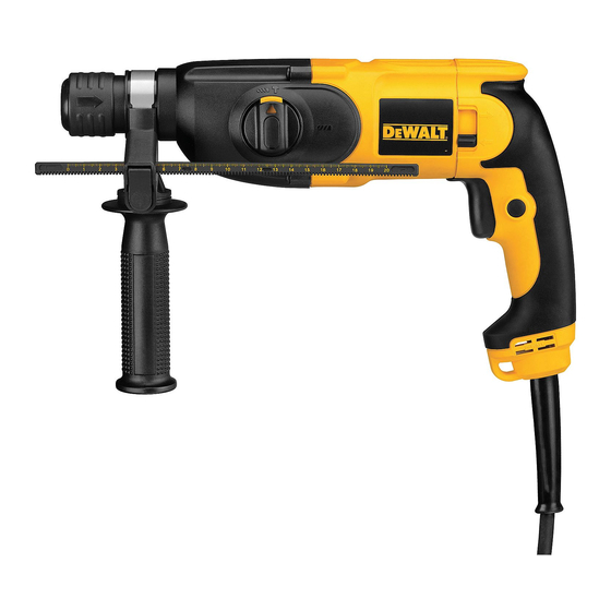
Model Visual Distinctions
Highlights visual differences between 22mm, 26mm, and 28mm models.
Before Repair and Service Procedures
Safety and Preparation Steps
Covers safety instructions and pre-repair checklist.
Electrical Safety and Testing
High Voltage Test Requirements
Explains the necessity and parameters for high voltage testing.
Pre-Repair Functional Checks
Unit Functionality Checklist
Lists essential functions to verify before service.
Troubleshooting: Root Cause Analysis
Identifying the Origin of Faults
Explains the process of finding the basic source of a problem.
Service Cleanliness Importance
Cleanliness for Durability
Stresses the impact of cleanliness on hammer durability.
Housing Disassembly: Screw Locations
Main Housing Screw Identification
Shows screw positions and types for housing removal.
Housing Separation and Internal View
Motor and Switch Assembly Access
Reveals internal components after housing separation.
Power Cord Management
Cable Securing and Strain Relief
Illustrates how the power cord is managed.
Switch Replacement Procedure
Switch Wiring and Tooling
Details switch terminal connections and required tools.
HPP D25263 Model Overview
Model and Specification Plate
Displays model number and technical specifications.
Rear Housing Disassembly
Rear Housing Screw Details
Shows screw locations and types for rear housing.
Switch and Capacitor Assembly
Capacitor Specifications
Details the rating of the capacitor.
Switch Terminal Wiring
Allen Key for Switch Connections
Illustrates using an Allen key for wiring.
Power Cord Entry and Securing
Cord Strain Relief Mechanism
Shows how the power cord entry is secured.
Main Body Disassembly: Screws
Main Body Screw Identification
Shows screw locations and types for the main body.
Chuck and Motor Housing Details
Motor Housing Components
Illustrates parts of the motor housing.
Carbon Brush Terminal Connections
Brush Holder Wiring
Shows electrical connections to brush holders.
Motor Carbon Brush Assembly
Carbon Brush Screw Specification
Details screw size for carbon brushes.
Motor Specifications and Identification
Model D25144-QS Nameplate
Displays nameplate details for a specific model.
Motor and Chuck Component Handling
Chuck Component Removal
Illustrates removing a chuck component.
Motor Assembly Alignment
Correct vs. Incorrect Alignment
Shows proper and improper motor component alignment.
Motor Housing Screw Specification
Screw Type 4x39.65 Tx20
Details a specific screw size for the motor housing.
Gear Housing and Motor Separation
Separating Mechanism Components
Illustrates separating the gear housing from the motor.
Gear Mechanism Components
Gear Housing Part Identification
Shows part number for the gear housing.
QCC (Quick Change Chuck) Operation
QCC Disassembly and Adjustment
Covers QCC disassembly and adjustment lever operation.
Hammer Mechanism Internal Components
Gear, Shaft, and Spring Assembly
Shows assembly of gears, shafts, and springs.
Hammer Mechanism Shaft Handling
Shaft Component Disassembly and Reassembly
Details steps for shaft component manipulation.
Component Pressing and Assembly
Hammer Mechanism Part Pressing
Shows using a tool to press mechanism parts.
Small Mechanism Component Identification
O-rings and Pins
Identifies small O-rings and pins used in the mechanism.
Gear Housing Assembly: Screw Installation
Gear Housing Screw Securing
Shows installation of screws into the gear housing.
Internal Hammer Mechanism Details
Lever and Spring Components
Shows specific lever and spring parts.
Gear Housing Assembly Steps
Gear Housing Screw Tightening
Illustrates tightening screws on the gear housing.
Gear Housing Assembly Screw Specification
Screw Type 4x9.2 Tx20
Details a specific screw size for the gear housing.
Hammer Mechanism Component Handling
Shaft, Gear, and Lubrication Steps
Covers shaft assembly, gears, and lubrication.
Motor and Housing Connection Points
Motor to Housing Interface
Shows the connection interface between motor and housing.
NQCC (Non Quick Change Chuck) Operation
NQCC Disassembly and Spring Replacement
Covers NQCC disassembly and spring component handling.
Service Resources and Final Steps
Online Support and Cleaning
Points to online resources and cleaning reminder.
Final Customer Check Reminder
Customer Inspection Importance
Stresses the importance of customer checks post-service.


Need help?
Do you have a question about the D25032K and is the answer not in the manual?
Questions and answers