Table of Contents
Advertisement
Quick Links
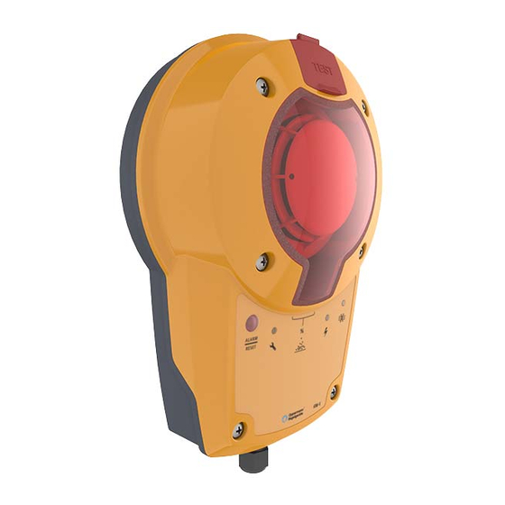
SENSOR CONSTRUCTION
1.
Adapter plate with gasket
2.
Patented measuring tube
3.
End cap
4.
Rubber bushing
(only for insulated or circular ducts)
5.
Housing base with gasket
6.
Electronics
7.
Optical smoke detector
8.
Housing top with gasket
9.
LED red: alarm/reset button
10. LED yellow: failure
11. LED display: sensor contamination in %
12. LED green: in operation
13. LWD blue: airflow below 1 m/s
14. Opening for test gas
15. Air duct
ASSEMBLING
Positioning of the sensor
The KRM-X must be positioned in accordance with the applicable local regulations on ventilation
systems. Reliable smoke detection must be ensured. The air collecting tube may be cut to a length of
160 mm, depending on the cross-section of the ventilation duct. It must not be cut to less than this
minimum length of 160 mm. Using the KS-X mounting bracket, this makes it possible to monitor ducts up
to <100 mm ø. There is no maximum width, height or diameter for air ventilation ducts monitored with the
600 mm long standard air collecting tube under the VdS approval/DIBt certification. The indicated airflow
direction must be observed when installing the tube adapter. The air collecting tube may be mounted
laterally, below or above the air duct – the location makes no difference.
In the ideal case, as far as is structurally possible, install the KRM-X in a location where flow meters etc.
are normally installed, so that there is a laminar airflow along the measuring tube. We recommend
mounting and installing the KRM-X at the same distance from heating, cooling and humidity devices and
in a similar way as flow sensors. The distance of the KRM-X to fittings, valves, filters, etc. should be 3
times the diagonal of the channel cross-section against the flow direction and 5 times with the flow
direction, if this is structurally possible. The KRM-X, including the air collecting tube, may not be installed
along the longitudinal edges of ventilation ducts (corner area). The KRM-X must be installed such that
the air collecting tube is constantly located in the air stream. In horizontal ventilation ducts the KRM-X,
including the air collecting tube, should be installed in the upper third of the ventilation duct or at the top
of the ventilation duct, if this is structurally possible.
Produal Oy
Keltakalliontie 18, 48770 Kotka FINLAND
Device assembly, wiring and commissioning can only be carried out by qualified professionals.
Always make the wirings while the power is switched off.
Example of positioning after the
change of air duct direction
5 d
h
Tel: +358 10 219 9100 / Fax: +358 5 230 9210
Information is subject to change without prior notice.
1
15
Air outlet
3 d
h
USER GUIDE
KRM-X-1 & KRM-X-2
V1.0 (07.05.2020)
14
11
10
Example of positioning after air
outlets.
5 d
h
www.produal.com
info@produal.fi
1 (9)
13
12
Advertisement
Table of Contents

Related Manuals for Produal KRM-X-2


Summarization of Contents
SENSOR CONSTRUCTION
Key Sensor Components
Lists primary parts like adapter plate, measuring tube, and housing.
Indicator Lights and Controls
Details the functions of LEDs (red, yellow, green, blue) and the reset button.
Test Gas Port
Describes the opening for introducing test gas for sensor verification.
ASSEMBLING
Assembly Safety Warning
Critical caution regarding qualified professionals and power disconnection.
Positioning of the sensor
General Placement Guidelines
Recommendations for optimal KRM-X sensor positioning in ventilation ducts.
Airflow and Duct Configuration
Guidance on positioning relative to airflow and duct features.
Positioning Examples
Visual illustrations of sensor placement scenarios.
Hydraulic Diameter Calculation
Explains how to determine hydraulic diameter for duct sizing.
Installation Examples and Procedure
Visual guides and step-by-step instructions for sensor mounting.
Measuring Tube Preparation
Instructions for adjusting the measuring tube length and end plug.
Adapter Plate and Duct Type Installation
Aligning the adapter plate and methods for rectangular/circular ducts.
Insulated Duct Installation Method
Procedure for mounting the sensor on insulated ventilation ducts.
Outdoor Environment Installation
Guidelines for installing the sensor in outdoor or cold conditions.
Housing Attachment and Wiring
Connecting the sensor housing and overview of electrical wiring.
Wiring Best Practices
Recommendations for field wiring, test/reset, and switching contacts.
PROGRAMMING BUS COMMUNICATION
Setting Bus Address and Speed
Procedure to configure communication parameters for specific models.
Automatic Value Saving
Information regarding the automatic saving of programmed values.
TESTING THE SENSOR
Functional Test and Test Gas Application
Steps for performing a basic operational check using test gas.
Alarm Reset and Recovery Procedures
How to reset alarms and handle persistent readings.
DISPLAY AND OPERATION
Device Controls and Display Meanings
Overview of physical controls and interpretation of digital display readouts.
Indicator Light Functions
Detailed explanation of the color-coded indicator lights' meanings.
Alarm/Reset and Flow Indicators
Functionality of the red alarm/reset and blue airflow LEDs.
Additional Indicator and Relay Behaviors
Further explanations for lights, and how relays/displays react to alarms/faults.
MAINTENANCE AND REPAIR
Testing and Contamination Monitoring
Annual testing requirements and monitoring of sensor contamination levels.
Maintenance Procedures and Safety
Steps and safety precautions before performing maintenance.
Pre-Maintenance Safety Checks
Essential safety measures before opening the device housing.
Sensor Replacement and Cleaning Procedures
Criteria for replacing the sensor and cleaning instructions.
Post-Maintenance Verification Checks
Checks for electrical connections, visual inspection, and system testing.
Downstream System and Network Checks
Verifying interaction with other systems and network recovery.
MODBUS COMMUNICATION
Modbus Protocol Properties
Configuration settings for the Modbus communication interface.
Modbus Function Code Overview
Explanation of the function codes used in Modbus communication.
Modbus Register Definitions
Detailed description of each Modbus holding register and its data.
Device Status and Smoke Detector Registers
Meaning of registers for device status and smoke detection value.
Contamination, Airflow, and Temperature Registers
Registers for contamination, airflow, and temperature readings.
Temperature Value Mapping
Table correlating Modbus register values to actual temperatures.
Need help?
Do you have a question about the KRM-X-2 and is the answer not in the manual?
Questions and answers