Advertisement
Quick Links
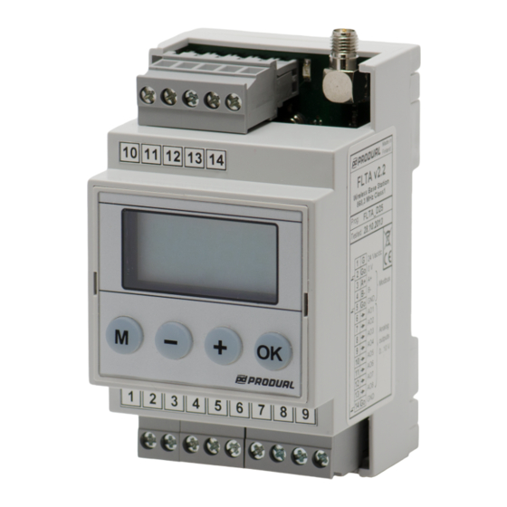
COMMISSIONING
Wiring
After switching power on for the first time, FLTA displays version number shortly and after that "SET" starts to flash.
- - - -
The base station settings can be configured through the menu. After configuring the settings, the transmitters and I/O
modules can be connected to the base station by using the FLSER commissioning tool. See the commissioning
instructions for transmitters and I/O modules from the documentation of the device in question.
Placing the FLAN antenna
The ideal FLTA antenna installation place is the central location in the network area. The antenna should be at least
10...15 cm away from the wall corner or concrete ceiling. The antenna should be installed on a large ferromagnetic
metal board (e.g. air duct inside a false ceiling) to create adequate anti-pole.
The default FLAN antenna cable length is 4 meters. If needed, the cable can be extended with FLANJJ-4,5 (4,5 m)
extension cable.
NOTE: Do not use more than one extension cable. All extra joints considerably dampen the radio signal.
Produal Oy
Keltakalliontie 18, 48770 Kotka FINLAND
Device wiring and commissioning can only be carried out by qualified professionals. Always make the
wirings while the power is switched off.
SET
Tel: +358 10 219 9100 / Fax: +358 5 230 9210
Information is subject to change without prior notice.
USER GUIDE
FLTA
V2.2 (24.09.2015)
info@produal.fi
www.produal.com
1 (9)
Advertisement

Related Manuals for Produal FLTA


Summary of Contents for Produal FLTA
- Page 1 Device wiring and commissioning can only be carried out by qualified professionals. Always make the wirings while the power is switched off. After switching power on for the first time, FLTA displays version number shortly and after that “SET” starts to flash. - - - - The base station settings can be configured through the menu.
- Page 2 RSSI 8 After testing, move the FLSER switch to OFF position. The base station is now ready for use. "On CARE” text disappears from the FLTA display. NOTE: If the network range is not adequate, a repeater is needed. Produal Oy...
-
Page 3: Analogue Outputs
If movement is not detected during next 4 minutes, the no detection information is sent to the base station. ”Detection” and ”no detection” information are delivered to the base station without delay. The FLTA analogue output delay (default = OFF (4 min) and selectable 5, 10, 15, 20, 25, 30 min) can be adjusted through the menu. -
Page 4: User Mode
4 (9) USER MODE The transmitter information is displayed on the FLTA base station display. The transmitter can be changed with ”+” ja ”-” buttons. With OK button it is possible to change the transmitter measurement information to be displayed. - Page 5 Disconnect the power supply from the unnecessary transmitter. Set the FLSER tool switch to the MID position. Push the + and - buttons to select the FLTA base station master ID (MID) from which you are removing the transmitter. MID= Push the OK button.
- Page 6 USER GUIDE FLTA 6 (9) MODBUS Modbus is in OFF mode as default. Modbus can be activated through the menu. NOTE: The Modbus mode affects to the alarm functions. See page 4, Alarms Bus properties Protocol RS-485 Modbus RTU...
- Page 7 USER GUIDE FLTA 7 (9) Discrete inputs Register Parameter description Data type Values Range 10001 SID 1, low battery 0 - 1 0: Off, 1: On 10002 SID 2, low battery 0 - 1 0: Off, 1: On …...
- Page 8 USER GUIDE FLTA 8 (9) Register Parameter description Data type Values Range 30052 SID 2, AO1 Signed 16 0…100 0,0…10,0 V 30053 SID 2, AO2 Signed 16 0…100 0,0…10,0 V … … 30244 SID 98, AO1 Signed 16 0…100 0,0…10,0 V...
- Page 9 USER GUIDE FLTA 9 (9) Notes Note Parameter description Data type Values Range Note 1 When the digital output SID(n) DO(x) is set to On, the analogue output SID(n) AO(x) is not in use When the digital output SID(n) DO(x) is set to Off, the analogue output SID(n) AO(x) is in use...
Need help?
Do you have a question about the FLTA and is the answer not in the manual?
Questions and answers