
Related Manuals for Montanari MGV25L


Summary of Contents for Montanari MGV25L
- Page 1 MANUALS INSTALLATION, USE AND MAINTENANCE GEARLESS MGV25 RANGE www.montanarigiulio.com...
- Page 2 You may check your supply, configure the inverter, download manuals, tech reports, certificates and much more. Search for Montanari Giulio App, available on Google Play and App store. SCAN THE QR TO DOWNLOAD SCAN THE QR TO DOWNLOAD...
- Page 3 We are proud to have you as a customer and user of the Montanari traction machines, and we are confident that we can work together for a long time. Thanks again for your choice.
- Page 4 REV. DATE DESCRIPTION EDITED BY VERIFIED BY APPROVED BY Technical Dept STEFANO BERTONI 25/03/2020 First Redaction Marketing Dept Alberto Mantovani (DTE) WARNING SYMBOLS USED IN THE MANUAL: It indicates that safety measures must be taken to avoid electric shock. It indicates that safety measures must be taken to prevent personal injury.
-
Page 5: Table Of Contents
ENGLISH MGV25 S-M-ML-L CONTENTS GENERAL INFORMATION ..............7 1.1 Introduction .................... 7 1.2 Copyright ....................7 SAFETY ....................8 2.1 Intended use ..................8 2.2 User’s obligations ................... 8 2.3 Correct disposal ................... 9 2.4 Specific hazards ..................9 2.5 Legal References ..................9 IDENTIFICATION AND DATA .............. - Page 6 OPERATION ..................27 8.1 Connections ..................27 8.2 Additional components ................ 27 8.3 General operation information ............. 27 TROUBLESHOOTING, MAINTENANCE AND REPAIR ......27 9.1 General information ................27 9.2 Traction/return sheave ................28 9.3 Replacement of components ............... 28 9.4 Problems, causes and solutions ............28 9.5 Maintenance and repair ...............
-
Page 7: General Information
1.2 Copyright All rights to these operating instructions belong to Montanari Giulio & C. S.r.l. The information in this manual may not be reproduced or used in an unauthori- zed manner or made available to third parties without prior approval. -
Page 8: Safety
Any modification by the user that may affect safety or reliability is prohibited; it is also prohibited to tamper with devices or functions designed to prevent accidental contact. The Montanari MGV25 gearless machine range must be used and operated in strict compliance with the conditions set out in the supply contract. -
Page 9: Correct Disposal
These plates must be kept clean and legible at all times. Missing plates must be replaced. • All spare parts can be obtained from Montanari Group. 2.3 Correct disposal Respect the environment and dispose of the product according to the regulations in force in the country of installation. - Page 11 ENGLISH MGV25 S-M-ML-L www.montanarigiulio.com...
-
Page 13: Dimensions
ENGLISH MGV25 S-M-ML-L 3.2 Dimensions The technical drawings and the overall dimensions follow. Tab. 9 Traction Sheave[mm] Dimensions [mm] Gearless Type Ø D MGV25S Fig. 2 MGV25S Ø 17, 5 115, 5 49,5 49,5 www.montanarigiulio.com... - Page 14 Tab. 10 MGV25M Pulley Ropes Dimensions ØD Ø min - max Pitch n° 3 - 8 9 - 10 3 - 8 9 - 10 3 - 8 9 - 10 3 - 6 Fig. 3 MGV25M Ø 17, 5...
- Page 15 ENGLISH MGV25 S-M-ML-L Tab. 11 MGV25ML - L Pulley Ropes Dimensions ØD Ø min - max Pitch n° 3 - 8 9 - 10 3 - 8 9 - 10 3 - 8 9 - 10 3 - 4 Fig. 4 MGV25ML - L Ø...
-
Page 16: Transport And Storage
Montanari Giulio & C. Observe the symbols on the packaging to prevent da- mage to property or personal injury. Here are the meanings of the symbols that may appear on the packaging. -
Page 17: Storage
ENGLISH MGV25 S-M-ML-L Fig. 5 For lifting, anchor points (eyebol- ts) are provided as shown in Fig. Use only the specified eyebolts to handle the unit. 4.2 Storage The gearless machine must be stored in the position of use on a wooden base not subject to vibrations, in a covered and sheltered place. -
Page 18: Description
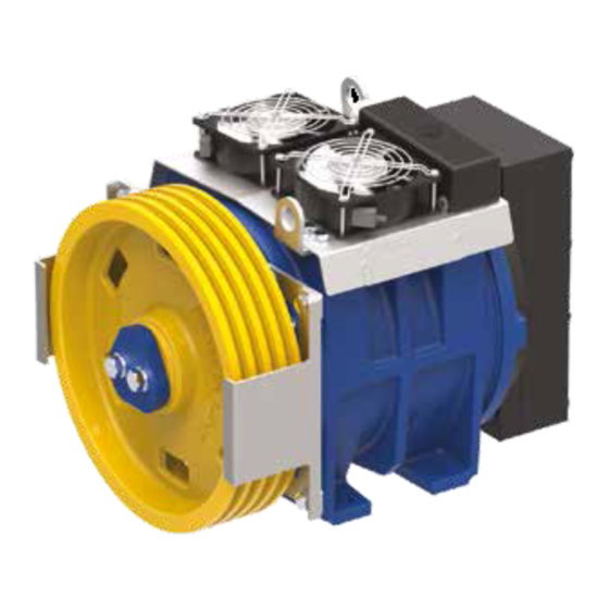
DESCRIPTION 5.1 General description The MGV25 series gearless machines are permanent magnet motors with dou- ble brake system. 5.2 Main components The unit consists of the main groups as shown in Fig. 6. MGV25 range is equipped with a PTC thermal probe inside the windings to protect against overheating (winding temperature up to 130°C) and with a ther-... -
Page 19: Brake
ENGLISH MGV25 S-M-ML-L 5.3 Brake The gearless machine is supplied with a brake that conforms to the standards indicated in paragraph 2.5. The brake system is pre-calibrated by the manufacturer and no further adjustment is required. The brake system operates as follows: •... -
Page 20: Installation Surface
The air supply for cooling must not be prevented. 6.2 Installation surface The installation surface must be uniform and level. The levelling tolerance is 0.1 mm. The installation surface must be rigid and robust enough to withstand the forces involved. 6.3 Installation procedure The gearless machine can be lifted using the eyebolts for the insertion of the belts or lifting chains (see also the paragraph on storage and handling). - Page 21 ENGLISH MGV25 S-M-ML-L Place the unit on the installation surface and secure it. • Fixing screws and nuts must be tightened to the prescribed torque. • Use bolts with a minimum strength class of 8.8. • Do not force or hit the fixings to position them; this could damage the bearings, rings, etc.
-
Page 22: Electrical Installation - Connections
6.4 Electrical installation - Connections The gearless machine is supplied with: • Cable for the power supply of the motor [1 - 2 - 3, Ground, SC] , for the power supply of the cooling fan (230 Vac) [F7-F8] and of the PTC guard [T5-T6] (Fig. 11). Cable Cooling fans cables (F7 - F8) [230Vac]... - Page 23 ENGLISH MGV25 S-M-ML-L Power supply Fig. 12 Brake Microswitch cable Blue Black Grey Coil power supply cable Blue Brown Standard mode: It is possible controlling only contactor 1 and leaving contactors 2 and 3 closed. (Fig. 13). This protects the brake from dangerous overvoltage and noise when closing. Emergency mode and inspection mode: The use of all contactors is recommended.
-
Page 24: Connection Of The Brake For Rescue System
CONNECTION OF THE BRAKE FOR RESCUE SYSTEM For installations with machine room, the cable and release lever are supplied as standard. The kit is shown in Fig. 15. Fig. 15 Connection cable Lever for manual for brake levers for Components for brake release. - Page 25 ENGLISH MGV25 S-M-ML-L MGV25M Fig. 17 MGV25ML-L Fig. 18 www.montanarigiulio.com...
-
Page 26: Connection Of The Cable To The Hand Release Lever
7.2 Connection of the cable to the hand release lever Fix the lever to the wall with Fig. 19 the bolts (not supplied). Connect the cable to the support as shown in Fig. 19. Insert the other end of the cable into the screw hole. -
Page 27: Operation
The bearings are protected and do not require any additional lubrication under standard conditions of use. Do not use high-pressure cleaners on the motor. Montanari cannot guarantee or be held responsible for unauthorized operations on the unit, improper use, modifications made without its consent or the use of non-genuine spare parts. -
Page 28: Traction/Return Sheave
Periodically, at least once a year, check the wear of the grooves in the traction sheave. In case of slipping ropes or excessive wear, contact Montanari Giulio & C. for replacement instructions, always indicating the serial number. 9.3 Replacement of components Instructions for the replacement of any component must be requested each time from the technical department specifying the serial number. -
Page 29: Maintenance And Repair
ENGLISH MGV25 S-M-ML-L 9.5 Maintenance and repair 9.5.1 General indications The unit must only be used, maintained and repaired by authorized, properly trained and qualified personnel. Compliance with the inspection and maintenance intervals is part of the condi- tions for the validity of the warranty. 9.5.2 Description of maintenance activities Stop the unit and put it out of service. -
Page 30: Spare Parts
10. SPARE PARTS 10.1 General information By keeping the main spare parts and wear parts in stock, the unit can always be used. 10.2 How to order spare parts The manufacturer guarantees only genuine spare parts and accessories sup- plied by him. Other parts not supplied by the manufacturer have not been tested or appro- ved. -
Page 31: Exam Certificate Eu-Bd 845 Mgv25S-M
ENGLISH MGV25 S-M-ML-L 11.1 Exam certificate EU-BD 845 MGV25S-M www.montanarigiulio.com... -
Page 32: Exam Certificate Eu-Bd 1014 Mgv25Ml-L
11.2 Exam certificate EU-BD 1014 MGV25ML-L... -
Page 33: Compliance Declaration
- UNI 10411-1; UNI 10411-3; UNI 10411-5; UNI EN 81-1:2010; UNI EN 81-20:2014 Note: As regards, the fulfillment of the paragraph 9.7 of the UNI EN81-1:2010 and 5.5.7 UNI EN81-20:2014, it is recalled that Montanari provides safety device only upon explicit request by the customer. Drafting: Signature: Stefano Bertoni –... - Page 34 MONTANARI GROUP HEADQUARTER Montanari Giulio & C. Srl Via Bulgaria 39 - 41122 - Modena - Italia Tel: +39 059 453611 - Fax: +39 059 315890 - info@montanarigiulio.com www.montanarigiulio.com...
Need help?
Do you have a question about the MGV25L and is the answer not in the manual?
Questions and answers