Table of Contents
Advertisement
All manuals and user guides at all-guides.com
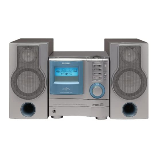
SERVICE MANUAL
COMPACT DISC
STEREO SYSTEM
SYSTEM
XS–G3(U,LH)
XS–G3(EZ,K)
XS–G4(EZ)
XS–G5(EZ)
XS–G5(K)
• This Service Manual is the "Revision Publishing" and replaces "Simple Manual"
XS-G3 (U,LH,EZ,K) / XS-G4 (EZ) / XS-G5 (EZ,K), (S/M Code No. 09-012-441-5T1).
• If requiring information about the CD mechanisim, see Service Manual of BZG-5,
(S/M Code No. 09-00C-353-3N2)
XS-G3
XS-G4
XS-G5
BASIC TAPE MECHANISM : BZM-1 R1NM
BASIC CD MECHANISM : BZG-5 ZD3NM
CD
SPEAKER
CASSEIVER
CX–G3
SX–G3
CX–G3
SX–G3
CX–G4
SX–G4
CX–G5
SX–G5
CX–G5
SX–G5
S/M Code No. 09-013-441-5R1
U,LH,EZ,K
EZ
EZ,K
REMOTE
CONTROLLER
RC–BAS11
RC–BAS03
RC–BAS11
RC–BAS11
RC–BAS03
Advertisement
Table of Contents

Related Manuals for Aiwa XS-G4 EZ


Summarization of Contents
SPECIFICATIONS
FM/AM/LW Tuner Specifications
Tuning range, sensitivity, and antenna details for FM, AM, and LW bands.
Amplifier & Speaker System Specs
Power output, harmonic distortion, speaker details, inputs, and outputs.
CD Player & General Specs
Details on CD player features, power requirements, and consumption.
LASER SAFETY PRECAUTIONS
Laser Beam Exposure Warnings
Cautionary notes regarding laser beam exposure during servicing.
Optical Block Replacement Safety
Precautions when handling and replacing the optical block.
REPAIR PREPARATION AND MICROCOMPUTER CHECKS
Capacitor Discharge Procedure
Steps to safely discharge capacitors before repair.
Microcomputer Pre-Exchange Checks
Verifying microcomputer status before replacement.
Microcomputer Reset and Soldering Checks
Procedures for resetting and checking microcomputer solder.
DISASSEMBLY INSTRUCTIONS
Mechanism Deck Disassembly Steps
Step-by-step guide to disassemble the mechanism deck.
ASSEMBLY INSTRUCTIONS
Mechanism Deck Assembly Steps
Step-by-step guide for assembling the mechanism deck.
LCD DISPLAY INFORMATION
LCD Segment Wiring
Diagram showing connections for each LCD segment.
LCD Common Wiring
Diagram showing common wiring for the LCD.
ADJUSTMENT PROCEDURES
Tuner Section Adjustments
Procedures for adjusting tuner parameters.
Deck Section Adjustments
Procedures for adjusting tape deck functions.
Front Section Adjustments
Procedure for µ-CON OSC adjustment.
CD TEST MODE OPERATIONS
CD Test Mode Start/Exit
Instructions for entering and exiting CD test mode.
CD Test Mode Functions & Checks
Description of test modes and their checks.
AUTOMATIC ADJUSTMENT RESULT DISPLAY
Focus Result Display
How to view focus adjustment results.
Tracking Result Display
How to view tracking adjustment results.
SPEAKER DISASSEMBLY INSTRUCTIONS
Speaker Unit Removal
Methods for removing speaker units.
Front Panel Removal/Attachment
Steps for front panel disassembly and assembly.
Need help?
Do you have a question about the XS-G4 EZ and is the answer not in the manual?
Questions and answers