JVC KS-RF37 Service Manual

JVC KS-RF37 Service Manual

Compact disc automatic changer

Advertisement

SERVICE MANUAL
COMPACT DISC AUTOMATIC CHANGER
CH-X1000 / CH-X1000RF
CH-X1000RF is a combination of CH-X1000 and KS-RF37.
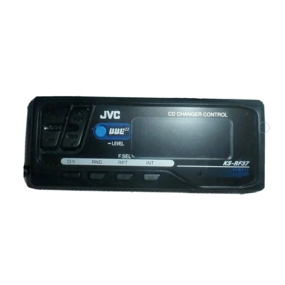
KS-RF37 is a combination of Remote control and the RF unit.
Contents
Safety precaution
Important for laser products
Location of main parts
Removal of main parts
Pickup replacement procedure
JC 12 Forced eject procedures
KS-RF37
1-2
1-3
1-4
1-5
1-18
1-20
This service manual is printed on 100% recycled paper.
COPYRIGHT
2001 VICTOR COMPANY OF JAPAN, LTD.
J
CH-X1000
Troubleshooting
Wiring connections
Description of major ICs
CH-X1000 /X000RF
Area Suffix
Northern America
1-21
1-27
1-28
No.49594
Feb. 2001

Advertisement

Table of Contents
loading
Need help?

Need help?

Do you have a question about the KS-RF37 and is the answer not in the manual?

Questions and answers

Summarization of Contents

Location of Main Parts
Bottom View
Shows the layout of components from the bottom of the unit.
Top Side View
Displays the mechanism and magazine house section from the top.
Remove the Main Board View
Illustrates main parts like motors and gears after main board removal.
Removal of Main Parts
Disassembling Procedures
General instructions for disassembling various components.
Replacement of the Pickup
Step-by-step guide for replacing the pickup assembly.
Mechanism Section
Procedures for removing and servicing the internal mechanism.
Exterior Section
Steps to remove external parts like covers and panels.
Removing the Bottom Cover and Front Panel Assembly
Detailed steps for removing the bottom and front panels.
Removing the Top Cover
Instructions for removing the top cover and damper brackets.
Changer Mechanism Section
Procedures for accessing and removing mechanism components.
Sensor Assembly Unit
Steps to remove the sensor assembly unit.
Magazine Lock Arm
Instructions for removing the magazine lock arm.
Positioning Motor Assembly
Steps for removing the positioning motor assembly.
Rear Slider
Procedure to remove the rear slider component.
Front Slider
Procedure to remove the front slider component.
Top Plate
Steps to remove the top plate and its connected parts.
Lifter Unit
Instructions for removing the lifter unit from the chassis.
Lifter Bracket
Steps to remove the lifter bracket.
Side Bracket and Traverse Mechanism
Procedures for removing side bracket and traverse mechanism.
Pickup Assembly
Detailed steps for removing the pickup assembly.
Tray Motor
Procedures to remove the tray motor and its assembly.
Separation of the Chassis L Assembly and Chassis R Assembly
Steps to separate chassis L and R assemblies.
Precautions On Reassembling
Mounting the Traverse Mechanism
Steps for reassembling the traverse mechanism.
Mounting the Lifter Unit
Instructions for reassembling the lifter unit.
Connection of the Chassis L and R Assemblies
Steps to connect the chassis L and R assemblies.
Mounting the Top Plate
Steps to reassemble the top plate and upper rod.
Mounting the Front Slider and Rear Slider
Procedures for reassembling front and rear sliders.
Mounting the Sensor PCB Assembly
Steps to reassemble the sensor PCB assembly.
Mounting the Main PC Board Assembly
Procedures for reassembling the main PC board assembly.
Troubleshooting
Other Errors Occurring in the Receiver or Controller
Discusses general connection and power errors.
CH-1 Error Code Table
Lists error codes and their generating conditions for troubleshooting.
Wiring Connections
Wiring of Mechanism Board Section
Diagram showing wiring connections for the mechanism board.
Description of Major ICs
IC581 (BA5926S) Details
Covers Terminal Layout, Block Diagram, and Pin Function for IC581.
IC601 (UPD780058GC) Details
Details CPU IC601's Terminal Layout, Block Diagram, and Pin Function.
IC521 (TC9462F) Details
Covers RF amp IC521's Pin Layout, Block Diagram, and Pin Function.
IC501 (TA2109F) Details
Details RF amp IC501's Pin Layout, Block Diagram, and Pin Function.
IC604 (BR24C01AF) Details
Covers EEPROM IC604's Terminal Layout, Block Diagram, and Pin Function.
IC651 (HD74HC126FP) & IC602 (IC-PST600M/G/-W1197) Details
Details Buffer IC651 and Reset IC602 layouts, diagrams, and functions.

Table of Contents