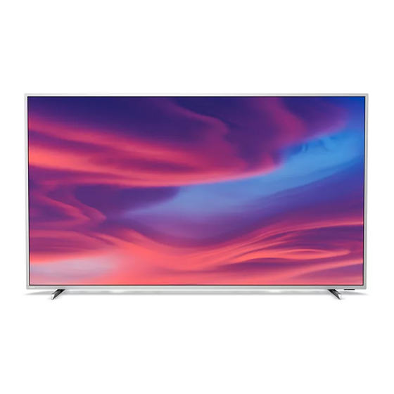
Table of Contents
Advertisement
Chassis name
TPM19.1A LA
Published by Doris.zheng /SC 2048 Quality
2019
TP Vision Netherlands B.V.
©
All rights reserved. Specifications are subject to change without notice. Trademarks are the
property of Koninklijke Philips Electronics N.V. or their respective owners.
TP Vision Netherlands B.V. reserves the right to change products at any time without being obliged to adjust
earlier supplies accordingly.
PHILIPS and the PHILIPS' Shield Emblem are used under license from Koninklijke Philips Electronics N.V.
Platform
MTK5599
Subject to modification
Model name
55PUT7374/98
55PUT7374/56
55PUT7374/67
55PUT7374/79
55PUT7374/75
55PUH7374/96
55PUT7374/68
65PUT7374/98
65PUT7374/56
65PUT7374/67
65PUT7374/79
65PUT7374/75
65PUH7374/96
65PUT7374/68
70PUT7374/98
70PUT7374/56
75PUT7354/56
TPM19.1A
LA
Model name
70PUT7374/67
70PUT7374/79
70PUT7374/75
70PUH7374/96
55OLED804/98
55OLED804/56
55OLED804/67
55OLED804/75
55OLED804/79
55OLED804/71
65OLED804/98
65OLED804/56
65OLED804/67
65OLED804/75
65OLED804/79
65OLED804/71
3122 785 20991
2020-Oct-20
Advertisement
Table of Contents

Summarization of Contents
2. Precautions, Notes, and Abbreviation List
2.1 Safety Instructions
Safety regulations for repair, wiring, and insulation checks.
2.2 Warnings
Warnings regarding electrostatic discharge, high voltage, and component handling.
2.4 Abbreviation List
List of abbreviations used in the manual for technical terms.
3. Mechanical Instructions
3.1 Cable Dressing
Details on routing and securing cables within the TV chassis for different models.
3.2 Assembly/Panel Removal
Procedures for disassembling and removing TV components like the stand and rear cover.
4. Service Modes
4.2 Service Alignment Mode (SAM)
Mode for modifying NVM, clearing error codes, and performing alignments.
4.3 Factory mode
Mode for extended alignments, panel/tuner ID changes, and error buffer clearing.
4.4 Customer Service Mode (CSM)
Read-only mode displaying error codes and settings for customer support.
5. Software Upgrading, Error code and Panel Code
5.1 Software Upgrading
Step-by-step guide for updating TV software using USB drives.
5.2 Error Code
Explanation and overview of error codes indicating TV failures.
5.3 Set Option Code
Procedure for setting the option code based on the panel type.
7. Electrical Diagram
7.1 Block diagram
A visual representation of the TV's main functional blocks and their connections.
7.2 Power Supply
Overview of the power architecture of the platform.
7.3 Power tree
Detailed breakdown of power distribution across various components and voltage rails.
8. IC Data Sheets
8.1 MT5599IFEQ (IC U401--Scaler)
Data sheet information for the MT5599IFEQ scaler IC.
8.2 TAS5760LDDCAR (IC U5100--Audio)
Data sheet information for the TAS5760LD audio IC.
8.3 SI2169-D60-GMR (U201)
Functional block diagram for the SI2169-D60-GMR tuner/demod IC.
9. Circuit Diagrams
9.1 A 715GA018 PSU (For 55”/65” 7374 Series)
Circuit diagram for the PSU (Power Supply Unit) used in 55"/65" 7374 series models.
9.2 A 715GA025 PSU (For 70” 7374 & 75” 7354 Series)
Circuit diagram for the PSU (Power Supply Unit) used in 70"/75" 7374 & 7354 series models.
9.3 A 715G9892 PSU (For 55”/65” OLED Series)
Circuit diagram for the PSU (Power Supply Unit) used in 55"/65" OLED series models.
9.4 B 715GA006M SSB(For 7374/7354 series)
SSB (Small Signal Board) schematic for 7374/7354 series.
9.5 B 715GA046M SSB(For OLED Series)
SSB (Small Signal Board) schematic for OLED series.
10. Styling Sheets
10.1 7374 series 55"
Exploded view and parts list for the 55" 7374 series TV.
10.2 7374 series 65"
Exploded view and parts list for the 65" 7374 series TV.
10.3 7374 series 70"
Exploded view and parts list for the 70" 7374 series TV.
10.4 OLED804 series 55"
Exploded view and parts list for the 55" OLED804 series TV.


Need help?
Do you have a question about the 65PUT7374/98 and is the answer not in the manual?
Questions and answers