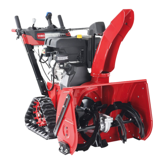
Summarization of Contents
Chapter 1 Safety
Safety Instructions
Explains the meaning of DANGER, WARNING, and CAUTION safety symbols.
Think Safety First - Operational Safety
Covers safety related to parts, bystanders, projectiles, modifications, operation, and electrical shock.
Think Safety First - System Safety
Safety advice for hydraulic systems, PPE, tools, lifting equipment, and fire extinguishers.
Chapter 2 Specifications and Maintenance
Machine Specifications
Details specifications for POWER TRX™ models including clearing width, engine, and dimensions.
Torque Specifications
Torque values for inch and metric fasteners based on grade and thread size.
Specialized Fastener Torque
Torque values for specialized fasteners like SAE Grade 8, wheel bolts, and thread cutting screws.
Measurement Conversions
Conversion table for fractional measurements to decimals and millimeters.
U.S. to Metric Conversions
Conversion factors for converting U.S. customary units to metric units.
Chapter 3 Troubleshooting
General Troubleshooting
Guidance on troubleshooting procedures, referring to the Operator's Manual.
Chapter 4 Engine
Engine General Information
Information on Toro Engine models used in POWER TRX™ units and their starter types.
Engine Assembly
Exploded view and list of components for engine assembly.
Engine Removal and Installation
Step-by-step instructions for removing and installing the engine.
Chapter 5 Track Drive System
Track Drive General Information
Explains that the track drive system uses hydro bypasses for the wheel clutch system.
Track Drive Assembly
Exploded view of track drive components with a numbered parts list.
Hydro Assembly
Exploded view of the hydro unit and its associated brackets.
Track Replacement Procedure
Step-by-step instructions for removing and installing the snow tracks.
Hydro Replacement Procedure
Step-by-step instructions for removing and installing the hydro unit.
Chapter 6 Controls
Controls General Information
States that POWER TRX™ models feature commercial grade handles and controls.
QUICK STICK® Assembly
Exploded view of the QUICK STICK® assembly with a numbered parts list.
Handle Bracket Assembly
Exploded view of the handle bracket assembly with a numbered parts list.
QUICK STICK® Replacement
Instructions for removing, disassembling, and installing the QUICK STICK® control.
Control Interlock Replacement
Steps for removing and installing the control interlock system.
Deflector Cable Adjustment
Procedure for adjusting the deflector cable for proper chute control.
Shift Lever Adjustment
Instructions for adjusting the shift lever and rod for proper gear engagement.
Chapter 7 Belts
Belts General Information
States that POWER TRX™ units utilize a double-V auger drive belt.
Auger Drive Components
Exploded view of auger drive components with a numbered parts list.
Auger Belt Replacement
Step-by-step instructions for removing and installing the auger belt.
Traction Belt Replacement
Step-by-step instructions for removing and installing the traction belt.
Chapter 8 Auger Housing
Auger Housing General Information
Mentions the new gearcase featuring a horizontal parting line and heavy duty steel gears.
Main Frame and Auger Housing Assembly
Exploded view of the main frame and auger housing assembly with parts.
Fixed Scraper and Replacement
Description of the fixed scraper and its adjustable mounting for replacement.
Chapter 9 Auger Gearbox
Auger Gearbox General Information
Describes the auger gearbox containing worm and helical gears, driven by a clutching belt.
Auger and Impeller Assembly
Exploded view of the auger, impeller, and gearbox components.
Separating Auger and Traction Assemblies
Step-by-step instructions for separating the auger and traction assemblies.
Auger Gear Box Replacement
Instructions for installing the auger gearbox, including shaft preparation and securing.
Chapter 10 Discharge Chute
Discharge Chute General Information
States that POWER TRX™ snow blowers feature steel discharge chutes.
Chute Assembly
Exploded view of the chute assembly with a numbered parts list.
Chute and Face Gear Cover Replacement
Step-by-step instructions for replacing the chute and face gear cover.
Chute Gear Replacement
Instructions for removing and installing the chute gear.
Appendix A Foldout Drawings
Electrical Drawing Abbreviations
Lists abbreviations used for wire harness colors in electrical schematics and drawings.
Electrical Schematic with Hand Warmers
Wiring diagram illustrating the electrical connections for hand warmers.
Electrical Schematic
Basic electrical schematic diagram of the system.


Need help?
Do you have a question about the Power TRX Commercial 1432 and is the answer not in the manual?
Questions and answers