Table of Contents
Advertisement
SERVICE MANUAL
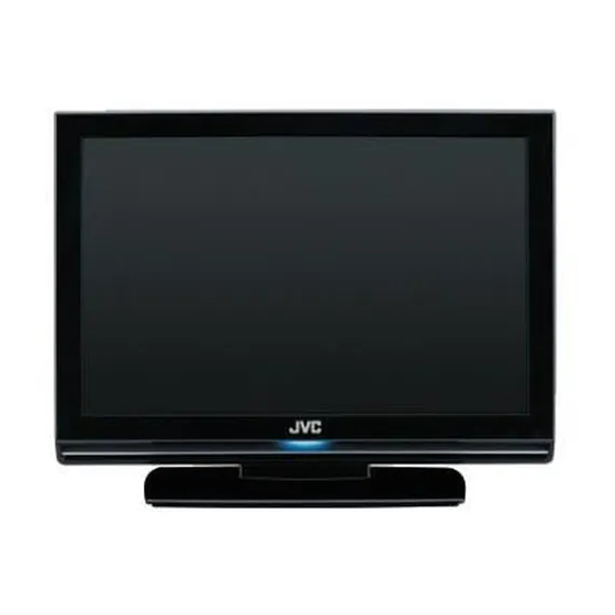
INTEGRATED DIGITAL TERRESTRIAL/SATELLITE LCD TELEVISION
8 S ERVICE MANUAL
YA606<Rev.002>
2008
LT-26DA9BJ, LT-26DA9BN,
LT-26DA9BU, LT-26DB9BD,
LT-26DC9BH, LT-26ED91U
COPYRIGHT © 2008 Victor Company of Japan, Limited
No.YA605: LT-19DA9/19DB9 series
No.YA607: LT-32DA9/32DB9/32DC9/32EP9U series
No.YA609: LT-26DE9 series
1
PRECAUTION. . . . . . . . . . . . . . . . . . . . . . . . . . . . . . . . . . . . . . . . . . . . . . . . . . . . . . . . . . . . . . . . . . . . . . . . . 1-4
2
SPECIFIC SERVICE INSTRUCTIONS . . . . . . . . . . . . . . . . . . . . . . . . . . . . . . . . . . . . . . . . . . . . . . . . . . . . . . 1-7
3
DISASSEMBLY . . . . . . . . . . . . . . . . . . . . . . . . . . . . . . . . . . . . . . . . . . . . . . . . . . . . . . . . . . . . . . . . . . . . . . 1-10
4
ADJUSTMENT . . . . . . . . . . . . . . . . . . . . . . . . . . . . . . . . . . . . . . . . . . . . . . . . . . . . . . . . . . . . . . . . . . . . . . . 1-15
5
TROUBLESHOOTING . . . . . . . . . . . . . . . . . . . . . . . . . . . . . . . . . . . . . . . . . . . . . . . . . . . . . . . . . . . . . . . . . 1-20
<MODEL LINEUP>
TABLE OF CONTENTS
COPYRIGHT © 2008 Victor Company of Japan, Limited
No.YA606: LT-26DA9/26DB9/32DC9/26ED91U series
No.YA608: LT-42DA9/42DB9 series
No.YA610: LT-32DE9 series
No.YA606<Rev.002>
2008/8
Advertisement
Table of Contents

Summarization of Contents
Section 1 PRECAUTION
1.1 Safety Precautions (Except for UK)
Safety precautions for product design, modifications, parts, and repair procedures.
1.2 Safety Precautions (For UK)
Safety precautions for product design, modifications, parts, and repair procedures for UK.
1.3 Installation Guidelines
Guidelines for heat dissipation, handling, and spatial requirements.
1.4 LCD Panel Handling Precautions
Precautions for transportation, optical filter care, and exterior part replacement.
Section 2 SPECIFIC SERVICE INSTRUCTIONS
2.1 Features Overview
Details about digital tuners, HDMI input, picture and sound modes.
2.2 Main Difference List
Compares key specifications across different JVC TV models.
2.3 21-Pin Euro Connector (SCART) Details
Pin assignments and signal matching for SCART connectors.
2.4 Technical Information
LCD panel specifications and pixel fault definitions.
Section 3 DISASSEMBLY
3.1 Disassembly Caution
General safety and handling precautions before beginning disassembly.
3.2 Disassembly Procedure
Step-by-step instructions for removing various parts and assemblies.
3.3 Memory IC Replacement and Settings
Procedure for memory IC replacement, factory mode settings, and shipment settings.
3.4 Chip Component Replacement
Cautions, soldering iron use, and steps for replacing chip components.
Section 4 ADJUSTMENT
4.1 Adjustment Preparation
Steps and conditions required before starting TV adjustments.
4.2 Preset Settings
Functions to preset before performing adjustments for optimal results.
4.3 Measuring Instruments
Lists required measuring instruments and fixtures for adjustments.
4.4 Adjustment Items
Specifies items for adjustment, including video circuit and white balance.
4.5 Factory Mode Operation and Settings
Instructions for factory mode access, value changes, and specific settings.
4.6 Setting Item in the Factory Mode
Comprehensive list of adjustable parameters in factory mode across various inputs.
4.7 Adjustment Procedure
Specific procedure for adjusting the video circuit, particularly white balance.
Section: Parts List
Caution for Parts List
Identifies parts critical for safety and notes parts availability.
Using P.W. Board & Remote Control Unit
Guide for using printed wiring boards and remote control units.
Exploded View Parts List
Lists parts shown in the exploded view diagrams.
Printed Wiring Board Parts List (Various Models)
Detailed parts lists for different PCB assemblies across various models.
Packing Parts List
Lists components included in the product packaging.
Section: Schematic Diagrams
Standard Circuit Diagram Notes
Explains symbols, values, and safety notes for circuit diagrams.
Circuit Diagrams
Circuit diagrams for Main, MPEG, IR, and Key PWB assemblies.
Pattern Diagrams
Solder and parts side patterns for Main and MPEG PWB assemblies.
Section: Wiring Diagram
Wiring Diagram Overview
Illustrates the interconnection between major boards and units.
Section: Block Diagram
System Block Diagram
Shows the overall functional blocks and data flow of the TV.
Section: PWB Circuit Diagrams
Main PWB Circuit Diagrams
Detailed circuit diagrams for the Main PWB assembly.
MPEG PWB Circuit Diagrams
Detailed circuit diagrams for the MPEG PWB assembly.
IR PWB Circuit Diagram
Circuit diagram for the IR PWB assembly.
Key PWB Circuit Diagram
Circuit diagram for the Key PWB assembly.
Section: PWB Patterns
Main PWB Patterns
Pattern layout for the Main PWB on the solder and parts sides.
MPEG PWB Patterns
Pattern layout for the MPEG PWB on the solder and parts sides.
IR and Key PWB Patterns
Visual patterns for IR and Key PWB on solder and parts sides.


Need help?
Do you have a question about the LT-32DA9 Series and is the answer not in the manual?
Questions and answers