Table of Contents
Advertisement
SERVICE MANUAL
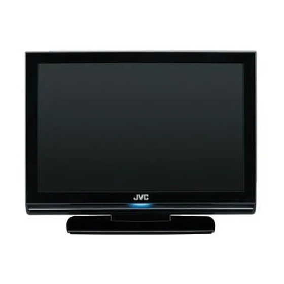
INTEGRATED DIGITAL TERRESTRIAL/SATELLITE LCD TELEVISION
8 S ERVICE MANUAL
YA606<Rev.002>
2008
LT-26DA9BJ, LT-26DA9BN,
LT-26DA9BU, LT-26DB9BD,
LT-26DC9BH, LT-26ED91U
COPYRIGHT © 2008 Victor Company of Japan, Limited
No.YA605: LT-19DA9/19DB9 series
No.YA607: LT-32DA9/32DB9/32DC9/32EP9U series
No.YA609: LT-26DE9 series
1
PRECAUTION. . . . . . . . . . . . . . . . . . . . . . . . . . . . . . . . . . . . . . . . . . . . . . . . . . . . . . . . . . . . . . . . . . . . . . . . . 1-4
2
SPECIFIC SERVICE INSTRUCTIONS . . . . . . . . . . . . . . . . . . . . . . . . . . . . . . . . . . . . . . . . . . . . . . . . . . . . . . 1-7
3
DISASSEMBLY . . . . . . . . . . . . . . . . . . . . . . . . . . . . . . . . . . . . . . . . . . . . . . . . . . . . . . . . . . . . . . . . . . . . . . 1-10
4
ADJUSTMENT . . . . . . . . . . . . . . . . . . . . . . . . . . . . . . . . . . . . . . . . . . . . . . . . . . . . . . . . . . . . . . . . . . . . . . . 1-15
5
TROUBLESHOOTING . . . . . . . . . . . . . . . . . . . . . . . . . . . . . . . . . . . . . . . . . . . . . . . . . . . . . . . . . . . . . . . . . 1-20
<MODEL LINEUP>
TABLE OF CONTENTS
COPYRIGHT © 2008 Victor Company of Japan, Limited
No.YA606: LT-26DA9/26DB9/32DC9/26ED91U series
No.YA608: LT-42DA9/42DB9 series
No.YA610: LT-32DE9 series
No.YA606<Rev.002>
2008/8
Advertisement
Table of Contents

Summarization of Contents
Section 1: Precaution and Safety Information
1.1 Safety Precautions (Except for UK)
Essential safety guidelines for handling and servicing the equipment, emphasizing original design and qualified personnel.
1.3 Installation Requirements
Guidelines for proper installation, heat dissipation, and secure placement to prevent accidents.
1.4 LCD Panel Handling Precautions
Procedures and warnings for safely handling, transporting, and cleaning the LCD panel to avoid damage.
Section 2: Specific Service Instructions
2.1 Features Overview
Details the digital tuning capabilities and HDMI input functionality of the television.
2.4 Technical Information
Provides LCD panel specifications and definitions for pixel faults (bright, dark, flicker).
Section 3: Disassembly and Component Replacement
3.1 Cautions During Disassembly
Critical safety warnings and preparation steps before disassembling the unit, including power disconnection.
3.2 Disassembly Procedures
Step-by-step instructions for removing various internal components and assemblies like covers and boards.
3.4 Chip Component Replacement
Guidelines and steps for safely soldering and desoldering surface-mount components like resistors and capacitors.
Section 4: Adjustment Procedures
4.1 Adjustment Preparation
Prerequisites and general notes before performing TV adjustments using the remote control unit.
4.6 Factory Mode Setting Items
Details setting items, ranges, default values, and comments for factory mode adjustments.
Parts List and Diagrams
Exploded View Parts List
Lists part numbers, names, descriptions, and local application for exploded view components.
Main PWB Circuit Diagrams
Detailed circuit schematics for various sections of the main Printed Wiring Board.
MPEG PWB Circuit Diagrams
Circuit diagrams for different modules of the MPEG Printed Wiring Board.
IR PWB Circuit Diagram
Schematic detailing the components and connections for the Infrared receiver PWB.
Key PWB Circuit Diagram
Diagram showing button connections, ADC values, and switch point settings for the key PWB.
Schematic Diagrams Overview
Standard Circuit Diagram Notes
Explains symbols, voltage values, and notations used in circuit diagrams for accurate interpretation.
Wiring and Block Diagrams
Overview of diagrams including semiconductor shapes, wiring, block, and circuit diagrams.
Main PWB Circuit Diagrams
Detailed circuit schematics for various sections of the main Printed Wiring Board.
MPEG PWB Circuit Diagrams
Circuit diagrams for different modules of the MPEG Printed Wiring Board.
IR PWB Circuit Diagram
Schematic detailing the components and connections for the Infrared receiver PWB.
Key PWB Circuit Diagram
Diagram showing button connections, ADC values, and switch point settings for the key PWB.


Need help?
Do you have a question about the LT-32DE9 Series and is the answer not in the manual?
Questions and answers