Table of Contents
Advertisement
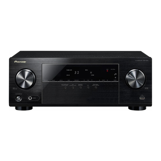
AV Receiver
VSX-323-K
THIS MANUAL IS APPLICABLE TO THE FOLLOWING MODEL(S) AND TYPE(S).
Model
Type
VSX-323-K
SYXE8
VSX-323-K
PWVXE8
VSX-323-K
DLXE
This service manual should be used together with the following manual(s).
Model No.
HTP-072/CMXESM
For SPECIFICATIONS and PANEL FACILITIES, refer to the operating instructions.
PIONEER CORPORATION
PIONEER ELECTRONICS (USA) INC. P.O. Box 1760, Long Beach, CA 90801-1760, U.S.A.
PIONEER EUROPE NV Haven 1087, Keetberglaan 1, 9120 Melsele, Belgium
PIONEER ELECTRONICS ASIACENTRE PTE. LTD. 253 Alexandra Road, #04-01, Singapore 159936
PIONEER CORPORATION
Power Requirement
AC 220 V to 230 V
AC 220 V to 240 V
AC 110 V to 127 V/220 V to 240 V
Order No.
RRV4432
VSX-324-K-P/YXE8, DLXE,
1-1, Shin-ogura, Saiwai-ku, Kawasaki-shi, Kanagawa 212-0031, Japan
2013
VSX-323-K
Remarks
PWXE
K-ZZZ MAY
ORDER NO.
RRV4438
Remarks
2013 Printed in Japan
Advertisement
Table of Contents

Related Manuals for Pioneer SYXE8


Summarization of Contents
Block Diagram
Overall Block Diagram
Provides a high-level overview of the VSX-323 AV receiver's functional blocks.
VCC Block Diagram
Illustrates the power supply distribution and voltage regulation for the VSX-323 unit.
GND Block Diagram
Details the ground connections and distribution across various sections of the VSX-323.
Schematic Diagram
Main Board Schematic (1/2)
Schematic diagram for the first half of the VSX-323 main circuit board.
Main Board Schematic (2/2)
Schematic diagram for the second half of the VSX-323 main circuit board.
Regulator Assembly Schematic
Schematic diagram for the VSX-323 regulator board.
PCB Connection Diagram
Regulator Assembly PCB Connection Diagram
Illustrates the physical connections on the VSX-323 regulator board.
Main Assembly PCB Connection Diagram
Shows the physical layout and connections on the VSX-323 main circuit board.
AMP5 Assembly PCB Connection Diagram
Diagrams showing the physical layout and connections for the VSX-323 AMP5 assembly.
G-L, G-R, and G-S Assemblies
Diagrams showing the physical layout of G-L, G-R, and G-S assemblies.
Need help?
Do you have a question about the SYXE8 and is the answer not in the manual?
Questions and answers