
Related Manuals for Gigabyte R181-NA0


Summarization of Contents
Chapter 1 Hardware Installation
1-1 Installation Precautions
Safety guidelines and precautions for hardware installation, emphasizing ESD protection.
1-2 Product Specifications
Detailed specifications for CPU, memory, storage, expansion slots, and connectivity.
1-3 System Block Diagram
Visual diagram illustrating the system's internal architecture and component connections.
Chapter 2 System Appearance
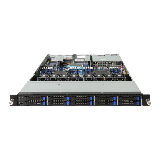
2-1 Front View
Illustration and description of the server's front panel components, including LEDs and ports.
2-2 Rear View
Illustration and description of the server's rear panel ports and connectors.
2-3 Front Panel LED and Buttons
Detailed explanation of front panel buttons and their associated LED status indicators.
2-4 Rear System LAN LEDs
Explanation of the status and functionality of rear system LAN LEDs.
2-5 Hard Disk Drive LEDs
Explanation of the status indicators for hard disk drives.
Chapter 3 System Hardware Installation
Pre-installation Instructions
Safety guidelines and precautions before starting hardware installation procedures.
3-1 Removing Chassis Cover
Step-by-step instructions for removing the server's front and rear chassis covers.
3-2 Removing and Installing the Fan Duct
Procedures for removing and installing the internal fan duct assembly.
3-3 Installing the CPU and Heat Sink
Detailed instructions for installing the CPU and its associated heat sink.
3-4 Installing the Memory
Guidelines for installing DDR4 memory, including configurations and population rules.
3-5 Installing the PCI Expansion Card
Step-by-step guide for installing PCI expansion cards using riser assemblies.
3-6 Installing the Hard Disk Drive
Instructions for installing a 3.5" hard disk drive into the system's drive tray.
3-7 Installing the Mezzanine Card
Procedures for installing a mezzanine card onto the motherboard.
3-8 Replacing the FAN Assembly
Steps for removing and replacing the server's fan assembly.
3-9 Replacing the Power Supply
Instructions for safely removing and installing a replacement power supply unit.
3-10 Cable Routing
Guidelines and visual aids for proper routing of internal system cables.
Chapter 4 Motherboard Components
4-1 Motherboard Components
Identification and description of various motherboard connectors and components.
4-2 Jumper Setting
Configuration options and descriptions for motherboard jumpers.
Chapter 5 BIOS Setup
5-1 The Main Menu
Description of the BIOS Main Menu screen and navigation controls.
5-2 Advanced Menu
Submenu options for configuring various hardware components in the BIOS.
5-3 Chipset Setup Menu
Menu for configuring North Bridge and South Bridge chipset functions.
5-4 Server Management Menu
Setup menus for server-specific management features and options.
5-5 Security Menu
Options for setting up passwords to protect system access and BIOS settings.
5-6 Boot Menu
Configuration of drive priority and boot modes for system startup.
5-7 Save & Exit Menu
Options for saving changes, discarding changes, and exiting the BIOS setup.
5-8 BIOS POST Codes
Lists of POST codes for AMI Standard PEI, DXE, and error codes.
5-9 BIOS POST Beep code (AMI standard)
Beep codes indicating system status during POST for AMI standard.
5-10 BIOS Recovery Instruction
Instructions on how to restore the BIOS using the embedded recovery technique.
Need help?
Do you have a question about the R181-NA0 and is the answer not in the manual?
Questions and answers