Table of Contents
Advertisement
Quick Links
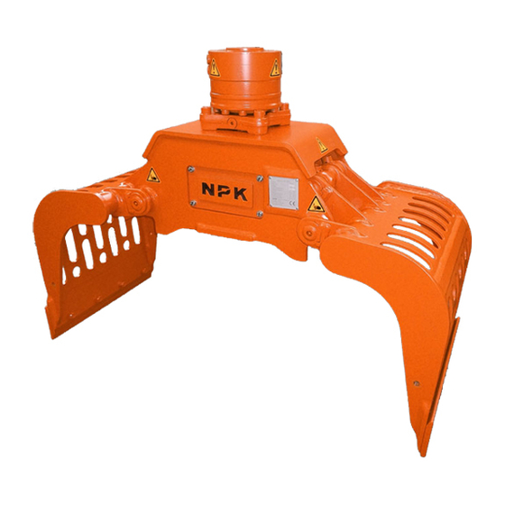
DEMOLITION GRAB
INSTRUCTION MANUAL
MODELS:
DG-4
DG-16
DG-30/30A DG-40/40A
© Copyright 2021 NPK Construction Equipment, Inc.
Grab Instruction Manual 6-21 All Models.docx
DG-6
DG-20/20A
"Use Genuine NPK Parts"
DG-9
Walton Hills, OH 44146-5541
www.npkce.com
DG000-9600D Demolition
DG-14
DG-25
DG-50
7550 Independence Drive
Phone (440) 232-7900
Fax (440) 232-6294
Advertisement
Table of Contents
Troubleshooting

Related Manuals for NPK DG-9


Summary of Contents for NPK DG-9
- Page 1 DG-14 DG-16 DG-20/20A DG-25 DG-30/30A DG-40/40A DG-50 “Use Genuine NPK Parts” 7550 Independence Drive Walton Hills, OH 44146-5541 Phone (440) 232-7900 Fax (440) 232-6294 © Copyright 2021 NPK Construction Equipment, Inc. www.npkce.com DG000-9600D Demolition Grab Instruction Manual 6-21 All Models.docx...
-
Page 2: Table Of Contents
FRAME CRACK REPAIR ........................31 LUBRICATION POINTS .......................... 32 SLEWING RING INSPECTION AND MAINTENANCE .................. 33 MEASURING MAXIMUM AXIAL MOVEMENT ..................33 NPK ASSEMBLY LUBRICANT ........................34 ROTARY JOINT MAINTENANCE ........................35 HYDRAULIC ROTARY JOINT ASSEMBLY.................... 35 LEAKAGE OF THE SEALS ........................35 TESTING THE ROTARY JOINT SEALS FOR INTERNAL LEAKAGE ........... -
Page 3: Safety
SAFETY Safety notices in NPK Instruction Manuals follow ISO and ANSI standards for safety warnings: DANGER (red) notices indicate an imminently hazardous situation which, if not avoided, will result in death or serious injury. WARNING (orange) notices indicate potentially hazardous situation which, if not avoided, could result in death or serious injury. -
Page 4: Operation
SAFETY OPERATION 1. Operator personnel must read and understand the NPK INSTRUCTION MANUAL to prevent serious or fatal injury. 2. FLYING OR FALLING DEBRIS CAN CAUSE SERIOUS OR FATAL INJURY. Keep personnel and bystanders clear of the DEMOLITION GRAB while in operation. -
Page 5: Maintenance
NPK specifically disclaims any responsibility for bodily injury or Demolition Grab damage that results from the use of parts not sold or approved by NPK. 2. Use extreme caution in handling. A fully assembled Demolition Grab can weigh over 2 tons. - Page 6 SAFETY MAINTENANCE STANDARD PRACTICES ATTENTION Maintenance of and repairs to the Demolition Grab should be performed by an experienced service technician, thoroughly familiar with all standard practices and procedures, and most importantly, all safety precautions. The following is a review of common standard practices to be followed when working with hydraulic equipment and is not meant to be all-inclusive.
-
Page 7: Introduction
INTRODUCTION NPK prides itself on the design and manufacture of high-quality products. This tradition of quality workmanship and materials continues in our Demolition Grab. Many years of productive service can be realized with proper operation and care of the Demolition Grab. -
Page 8: Serial Number Location
SERIAL NUMBER LOCATION DG-4, DG-6, DG-9, DG-14, DG-16, DG-20/20A, DG-25, DG-30/30A, DG-40/40A, DG-50 sn2 – serial number tag... -
Page 9: Specifications
MODEL WEIGHT CLOSING CAPACITY MAXIMUM FORCE (volume) HOIST LOAD lbs. (kg) tonf (kN) (liter) lbs. (kg) DG-4 (172) (15) 0.12 (90) 1,650 (750) ROTATION: Rotation is 360° FLOW and PRESSURE SPECIFICATIONS: MODEL OIL FLOW PRESSURE MAIN JAWS MAIN JAWS (lpm) - Page 10 SPECIFICATIONS MODEL WEIGHT CLOSING CAPACITY MAXIMUM FORCE (volume) HOIST LOAD lbs. (kg) tonf (kN) (liter) lbs. (kg) DG-6 (290) (21) 0.20 (150) 3,300 (1,500) ROTATION: Rotation is 360° FLOW and PRESSURE SPECIFICATIONS: MODEL OIL FLOW PRESSURE MAIN JAWS MAIN JAWS (lpm) (bar) DG-6...
- Page 11 SPECIFICATIONS MODEL WEIGHT CLOSING CAPACITY MAXIMUM FORCE (volume) HOIST LOAD lbs. (kg) tonf (kN) (liter) lbs. (kg) DG-9 (450) (32) 0.24 (180) 3,307 (1,500) ROTATION: Rotation is 360° FLOW and PRESSURE SPECIFICATIONS: MODEL OIL FLOW PRESSURE MAIN JAWS MAIN JAWS (lpm) (bar) DG-9...
- Page 12 SPECIFICATIONS MODEL WEIGHT CLOSING CAPACITY MAXIMUM FORCE (volume) HOIST LOAD lbs. (kg) tonf (kN) (liter) lbs. (kg) DG-14 1,415 (642) (38) (300) 6,614 (3,000) ROTATION: Rotation is 360° FLOW and PRESSURE SPECIFICATIONS: MODEL OIL FLOW PRESSURE MAIN JAWS MAIN JAWS (lpm) (bar) DG-14...
- Page 13 SPECIFICATIONS MODEL WEIGHT CLOSING CAPACITY MAXIMUM FORCE (volume) HOIST LOAD lbs. (kg) tonf (kN) (liter) lbs. (kg) DG-16 1,930 (875) (48) (425) 7,716 (3,500) ROTATION: Rotation is 360° FLOW and PRESSURE SPECIFICATIONS: MODEL OIL FLOW PRESSURE MAIN JAWS MAIN JAWS (lpm) (bar) DG-16...
- Page 14 SPECIFICATIONS MODEL WEIGHT CLOSING CAPACITY MAXIMUM FORCE (volume) HOIST LOAD lbs. (kg) tonf (kN) (liter) lbs. (kg) DG-20/20A 2,756 (1,250) (52) (500) 9,920 (4,500) ROTATION: Rotation is 360° FLOW and PRESSURE SPECIFICATIONS: MODEL OIL FLOW PRESSURE MAIN JAWS MAIN JAWS (lpm) (bar) DG-20/20A...
- Page 15 SPECIFICATIONS MODEL WEIGHT CLOSING CAPACITY MAXIMUM FORCE (volume) HOIST LOAD lbs. (kg) tonf (kN) (liter) lbs. (kg) DG-25 3,216 (1,450) (60) (600) 9,920 (4,500) ROTATION: Rotation is 360° FLOW and PRESSURE SPECIFICATIONS: MODEL OIL FLOW PRESSURE MAIN JAWS MAIN JAWS (lpm) (bar) DG-25...
- Page 16 SPECIFICATIONS MODEL WEIGHT CLOSING CAPACITY MAXIMUM FORCE (volume) HOIST LOAD lbs. (kg) tonf (kN) (liter) lbs. (kg) DG-30/30A 4,078 (1,850) (72) 1.05 (800) 12,125 (5,500) ROTATION: Rotation is 360° FLOW and PRESSURE SPECIFICATIONS: MODEL OIL FLOW PRESSURE MAIN JAWS MAIN JAWS (lpm) (bar) DG-30/30A...
- Page 17 SPECIFICATIONS MODEL WEIGHT CLOSING CAPACITY MAXIMUM FORCE (volume) HOIST LOAD lbs. (kg) tonf (kN) (liter) lbs. (kg) DG-40/40A 4,519 (2,050) (72) 1.18 (900) 12,125 (5,500) ROTATION: Rotation is 360° FLOW and PRESSURE SPECIFICATIONS: MODEL OIL FLOW PRESSURE MAIN JAWS MAIN JAWS (lpm) (bar) DG-40/40A...
- Page 18 SPECIFICATIONS MODEL WEIGHT CLOSING CAPACITY MAXIMUM FORCE (volume) HOIST LOAD lbs. (kg) tonf (kN) (liter) lbs. (kg) DG-50 5,512 (2,500) 10.1 (90) 1.44 (1100) 12,125 (5,500) ROTATION: Rotation is 360° FLOW and PRESSURE SPECIFICATIONS: MODEL OIL FLOW PRESSURE MAIN JAWS MAIN JAWS (lpm) (bar)
-
Page 19: Hydraulic Installation
HYDRAULIC INSTALLATION HYDRAULIC LINES Typically, the pressure line to close is arranged on the left side of the boom and the open line is on the right side. SHUT-OFF VALVES Some hydraulic installation kits use two shut-off valves (k4) on the dipper stick (k1) of the carrier. -
Page 20: Port Connection Diagram
PORT CONNECTION DIAGRAM HOSE: arm close HOSE: arm open m39a ROTATION HOSE: for clockwise movement m39b ROTATION HOSE: for counterclockwise movement MODEL OPEN/CLOSE ROTATION DG-4 8 JIC 8 JIC DG-6 8 JIC 8 JIC DG-9 8 JIC 8 JIC DG-14... -
Page 21: Demolition Grab Hydraulic Circuits
DEMOLITION GRAB HYDRAULIC CIRCUITS CYLINDER HYDRAULIC CIRCUIT ROTARY JOINT ASSEMBLY CYLINDER COUNTERBALANCE VALVE ARM CLOSE PORT ARM OPEN PORT... - Page 22 DEMOLITION GRAB HYDRAULIC CIRCUITS SINGLE MOTOR HYDRAULIC CIRCUIT HYDRAULIC MOTOR FLOW REGULATOR CROSS PORT RELIEF m39a CLOCKWISE ROTATION PORT m39b COUNTER-CLOCKWISE ROTATION PORT...
- Page 23 DEMOLITION GRAB HYDRAULIC CIRCUITS DUAL MOTOR HYDRAULIC CIRCUIT HYDRAULIC MOTOR CROSS PORT RELIEF m39a CLOCKWISE ROTATION PORT m39b COUNTER-CLOCKWISE ROTATION PORT...
-
Page 24: Mounting Installation
MOUNTING INSTALLATION NPK Mounting Installation Kits include the parts required to adapt the NPK Demolition Grab to the stick or arm of the excavator. The kits include all necessary stick and link pins, bolts, etc. STICK PIN (optional) LINK PIN (optional) -
Page 25: Mounting To The Excavator
MOUNTING INSTALLATION MOUNTING TO THE EXCAVATOR 1. Position the Demolition Grab on wood blocks (t20) as shown. 2. Align the stick pin bore (m24). Install the stick pin (m1). 3. Align the link pin bore (m25). Install the link pin (m2). 4. -
Page 26: Operating Instructions
OPERATING INSTRUCTIONS Before operating the NPK Demolition Grab, be sure to read the safety information and perform the daily and weekly maintenance as specified in this manual. DO NOT OPERATE THE DEMOLITION GRAB WITHOUT DEMOLITION GUARDS IN PLACE! DO NOT LIFT OR LOAD BEYOND THE CAPACITY OF THE... - Page 27 USE THE DEMOLITION GRAB ONLY FOR THE APPLICATION FOR WHICH IT IS INTENDED: • The NPK Demolition Grab is an attachment which is designed for grabbing and moving of materials which are on a solid base, under water or in a construction setting, but in such a way, that no danger is caused to the surroundings and operators.
-
Page 28: Operating Techniques And Precautions
OPERATING INSTRUCTIONS OPERATING TECHNIQUES AND PRECAUTIONS ATTENTION Do not use the Demolition Grab with the excavator cylinders fully extended (96) or retracted (97). Do not strike the material with the Demolition Grab jaw set (DO1). Do not push, pull or scrape material with the Demolition Grab. - Page 29 1. Shut-off valve (k4) must be in the off (k6) position for use with the Demolition Grab. 2. Return line from hammer/compactor (Demolition Grab open) (FT). On some later NPK hydraulic kits, the lockout feature is done automatically using an accumulator isolation valve (k26).
- Page 30 Grasp the material to be grabbed as deep into the throat of the Demolition Grab as possible. Do not force the material into the jaws. If you have any questions on operating the Demolition Grab, please contact your local NPK dealer or call the NPK Service Department at (440) 232-7900.
-
Page 31: General Maintenance
GENERAL MAINTENANCE REFER TO IMPORTANT SAFETY INFORMATION SECTION DAILY INSPECTION AND MAINTENANCE The functions that the Demolition Grab performs are demanding jobs in tough environments. Therefore, it is extremely important that the following maintenance and inspection procedures be performed daily. •... -
Page 32: Arm Maintenance
GENERAL MAINTENANCE ARM MAINTENANCE Check for wear of the replaceable cutters (dg3 and dg4). If the cutters no longer touch, they must be replaced. The diagram below shows new (CY) and worn (CZ) cutters. FRAME MAINTENANCE Inspect frame welds for cracks or other deformities. FRAME CRACK REPAIR 1. -
Page 33: Lubrication Points
GENERAL MAINTENANCE LUBRICATION POINTS GR1 Cylinder rod pin: one lubrication point located at drive arm attachment end. 10 strokes from grease gun every 4 hours. GR3 Jaw pivot pin: one lubrication point for each pin, located on main frame. 15 strokes from grease gun per fitting every 4 hours. GR4 Slewing ring/pinion teeth: three lubrication points on outside diameter of the slewing ring. -
Page 34: Slewing Ring Inspection And Maintenance
Using the excavator, slightly rock the Demolition Grab back and forth using slight stick movement. Note the movement shown by the dial. Take this reading (d59) in four places. If your readings are greater than shown, please contact the NPK Service Department at (440) 232-7900. MAXIMUM MODEL inch (mm) <.010 (0.25) -
Page 35: Npk Assembly Lubricant
3. Spray liberally on areas requiring lubrication. NPK ASSEMBLY LUBRICANT contains NPK-10 Metal Treatment and is ideal for use in the assembly of all NPK products. NPK ASSEMBLY LUBRICANT comes in a 16- ounce bottle with sprayer and can be ordered using part number H010-5010. -
Page 36: Rotary Joint Maintenance
ROTARY JOINT MAINTENANCE HYDRAULIC ROTARY JOINT ASSEMBLY The hydraulic rotary joint assembly (BN) is mounted inside the swivel top assembly (m27) which is under the top bracket (m7) that pins to the carrier and is bolted to the slewing ring (BT) which rotates the Demolition Grab’s main frame. -
Page 37: Replacement Of The Seals In The Rotary Joint
TESTING THE ROTARY JOINT SEALS FOR INTERNAL LEAKAGE PROCEDURE Install a 0 – 5,000 psi gauge (g8f) in the NPK shut-off (k4) located on the stick of the carrier. Close the arms and keep the function activated and read the pressure. - Page 38 ROTARY JOINT MAINTENANCE REPLACEMENT OF THE SEALS IN THE ROTARY JOINT Step 1 Remove the top bracket from the swivel flat top assembly. Remove the joint fitting adapter fittings (m44) from the spindle case manifold blocks. Remove the hoses (AO) from the spindle base manifold.
- Page 39 ROTARY JOINT MAINTENANCE REPLACEMENT OF THE SEALS IN THE ROTARY JOINT Step 3 Inspection: Visually inspect the sealing surfaces of the spindle (CA) for damage, which may hamper the ability of the main seals to seal. Polishing the surfaces (120) may clean up light scratching.
- Page 40 Lubricate the main seals (dg8), glide bearings (dg7) and o-rings (RR) with grease or NPK Assembly Lubricant. Install the main seals into the “Spindle Case” (BZ) first. Then install the first o-ring and glide bearing to the underside of the spindle case. Slide the “Spindle Case”...
-
Page 41: Troubleshooting
Qty. 1 -Pressure gauge: 0 – 5,000 psi (0 – 350 bar), for arm close circuit. Qty. 1 -Test port adapter: to fit #4 SAE female port in the NPK shut-off valve. Qty. 1 -Test hose: rated for 5,000 psi (350 bar). - Page 42 TROUBLESHOOTING RELIEF VALVE CHECKING AND SETTING PROCEDURE A. THE CARRIER’S HYDRAULIC CIRCUIT RELIEF VALVE Verify that the hydraulic circuit meets the Demolition Grab’s (GZ) requirements; see “SPECIFICATIONS”, pages 9 through 17. 1. Install a 0 – 5,000 psi (0 – 350 bar) pressure gauge (g8f) in the #4 SAE test port (k8) on the arm close side and a 0 –...
-
Page 43: Counterbalance Valve Location
TROUBLESHOOTING RELIEF VALVE CHECKING AND SETTING PROCEDURE B. DEMOLITION GRAB’S COUNTERBALANCE VALVE After the carrier’s hydraulic circuit has been verified, check the Demolition Grab’s counterbalance valve setting. 1. With the 0 – 5,000 psi (0 – 350 bar) gauge in the arm close side and the 0 – 5,000 psi (0 - 350 bar) in the arm open side of the stick, turn the shut-off valves (k4) to the “ON”... -
Page 44: Troubleshooting Chart For Low Power
Check the land Repair the land areas for the seals in areas or replace the the swivel manifold spindle. assembly. NOTE: If additional assistance is required, call the NPK Service Department at (440) 232-7900. -
Page 45: Checking Hydraulic Flow At Rated Pressure
Qty. 1 -Pressure gauge: 0 – 5,000 psi (0 – 350 bar), for arm close circuit. Qty. 1 -Test port adapter: to fit #4 SAE female port in the NPK shut-off valve. Qty. 1 -Test hose: rated for 5,000 psi (350 bar). - Page 46 TROUBLESHOOTING PROCEDURE FOR CHECKING HYDRAULIC FLOW AT RATED PRESSURE 4. To determine the available flow and relief valve setting of the carrier, follow the following procedure. a. Adjust the load valve on the flow meter to zero restriction. Start the carrier.
-
Page 47: Troubleshooting Chart For Slow Cylinder Speed
NOTE: If additional assistance is required, call the NPK Service Department at (440) 232-7900. JAW DRIFT 1. Some drift may be experienced depending on the Demolition Grab’s position. 2. Acceptable drift may occur over a number of minutes. -
Page 48: Rotation
Qty. 1 -Pressure gauge: 0 – 3,000 psi (0 – 210 bar) Qty. 1 -Gauge adapter fitting: 1/4” npt female x #6 JIC male (NPK part number K023-6690) Qty. 2 -Swivel run tee fittings: #8 JIC Qty. 2 -Test hoses: rated for 3,000 psi (210 bar); #8 JIC female swivel one end and #6... -
Page 49: Rotation Pressure Checking Procedure
TROUBLESHOOTING TROUBLESHOOTING FOR SLOW ROTATION SPEED ROTATION PRESSURE CHECKING PROCEDURE 1. Install gauges in the rotation circuit lines. 2. Position the Demolition Grab so that it will not rotate. 3. Attempt to rotate the unit in both directions. Each gauge should read 2,000 psi (138 bar). - Page 50 TROUBLESHOOTING ADJUSTMENT OF ROTATION SPEED DG-9, DG-14, DG-16 UNITS AND DG-20/20A, DG-25, DG-30/30A AND DG-40/40A UNITS WITH THE SINGLE MOTOR OPTION The rotation speed can be adjusted clockwise and counterclockwise independently from each other. PROCEDURE 1. Remove both covers (s9) from the side of the swivel top (m27). 2.
-
Page 51: Fastener Torque Charts
Threaded holes must be cleaned with a tap; then cleaned with solvent; then cleaned with compressed air. Do not use anti-seize compound on any fasteners, unless otherwise noted. TOP COVER - HHCS MODEL PART NO. BOLT DIA ft. lbs. (Nm) DG-4 DG-6 DG-9 DG-14 DG-16 71008020 (25) DG-20/20A 71008020... - Page 52 FASTENER TORQUE CHARTS SUPPORT BRACKET - HHCS MODEL PART NO. BOLT DIA. ft. lbs (Nm) DG-4 DG-6 74012055 (110) DG-9 71012025 (110) DG-14 DG-16 71012020 (110) DG-20/20A 71012020 (110) DG-25 71012020 (110) DG-30/30A 71012020 (110) DG-40/40A 71012020 (110) DG-50 71012020...
- Page 53 FASTENER TORQUE CHARTS PIN LOCK PLATE - HHCS MODEL PART NO. BOLT DIA. ft. lbs (Nm) DG-4 DG-6 DG-9 DG-14 74012025 (130) DG-16 74012025 (130) DG-20/20A 74012025 (130) DG-25 74012025 (130) DG-30/30A 74012025 (130) DG-40/40A 74012025 (130) DG-50 74012025 (130)
- Page 54 FASTENER TORQUE CHARTS SLEWING RING MODEL PART NO. BOLT DIA. ft. lbs (Nm) DG-4 DG-6 74012050 (130) DG-9 74012060 (130) 74016055 (350) DG-14 74016070 (350) DG-16 74016075 (350) 74016075 (350) DG-20/20A 74016070 (350) 74016075 (350) DG-25 74016070 (350) 74016080 (350)
-
Page 55: Pinion Gear Installation
PINION GEAR INSTALLATION Insert the key (c7) into the slot on the motor shaft. Next, slide the pinion gear (BR) onto the shaft. Lastly, apply a medium strength Loctite on the set screw (c6) and torque the set screw (c6) using the chart in the fastener torque section of this manual. -
Page 56: Cylinder Torque Specifications
The torques listed below, are for the rod nut (c1) and piston (c2) used in the cylinder assembly for the NPK Demolition Grab. When assembling during rebuild, it is also recommended that thread adhesive is used to ensure complete clamping. -
Page 57: Convert From Dual Motor To Single Motor (Dg20, Dg30, Dg40)
CONVERT FROM DUAL MOTOR TO SINGLE MOTOR (DG20, DG30, DG40) PARTS TO REMOVE 98500849 HOSE ASSEMBLY 9850201 HYDRAULIC MOTOR 98600640 PINION GEAR 98601199 MOTOR PLATE 98500155 97600055 SWIVEL ELBOW PARTS TO ADD 98601233 COVER 97600043 ADAPTOR FITTING 97600046 90° ADAPTOR 97600044 ADAPTOR FITTING 98500241... -
Page 58: Keywords For Common Demolition Grab Components
KEYWORDS FOR COMMON DEMOLITION GRAB COMPONENTS DG16 SHOWN MAIN FRAME ROTARY JOINT ASSEMBLY HYDRAULIC MOTOR PINION GEAR SLEWING RING CYLINDER PIN LOCK PLATE PIN (cylinder) DRIVE ARM dg10 LINK BUSHING CUTTER (sharp) CUTTER (blunt) SUPPORT BRACKET ARM PIN FRAME BUSHING PIN (cylinder rod end) hm21 MOTOR MOUNTING FLANGE... -
Page 59: Warranty Statements
WARRANTY STATEMENTS... - Page 60 WARRANTY STATEMENTS...
-
Page 61: Notes
NOTES NPK DEMOLITION GRAB MODEL NUMBER ________________ SERIAL NUMBER ______________________________________ NPK INSTALLATION KIT NUMBER ________________________ EXCAVATOR MANUFACTURER MODEL NUMBER SERIES SERIAL NUMBER DATE OF INSTALLATION __________ DATE OF 20 HOUR INSPECTION _________ WARRANTY REGISTRATION SENT ❑ SERVICE RECORD DATE... - Page 62 © Copyright 2021 NPK Construction Equipment, Inc. www.npkce.com DG000-9600D Demolition Grab Instruction Manual 6-21 All Models.docx...
Need help?
Do you have a question about the DG-9 and is the answer not in the manual?
Questions and answers