Table of Contents
Advertisement
INSTRUCTION MANUAL
AUTO LUBE SYSTEM
Hydraulically Actuated
© Copyright 2019 NPK Construction Equipment, Inc.
Mounted Auto Lube System 11-19
Hammer Mounted
"Use Genuine NPK Parts"
7550 Independence Drive
Walton Hills, OH 44146-5541
Toll-free (800) 225-4379
www.npkce.com
G025-9600g Hammer
Phone (440) 232-7900
Fax (440) 232-6294
Advertisement
Table of Contents

Related Manuals for NPK G015


Summary of Contents for NPK G015
- Page 1 AUTO LUBE SYSTEM Hammer Mounted Hydraulically Actuated “Use Genuine NPK Parts” 7550 Independence Drive Walton Hills, OH 44146-5541 Phone (440) 232-7900 Toll-free (800) 225-4379 Fax (440) 232-6294 © Copyright 2019 NPK Construction Equipment, Inc. www.npkce.com G025-9600g Hammer Mounted Auto Lube System 11-19...
-
Page 2: Table Of Contents
INSTALLATION INSTRUCTIONS ......................18 G015 ................................ 18 For NPK 500 to 1300 ft. lb. class hammers (with fixed hammer port connections)......18 For NPK 500 to 1300 ft. lb. class hammers (with swivel hammer port connections)......22 For NPK 2000 ft. lb. class hammers (with top brackets that include joint fittings)......25 G025 ................................ - Page 3 THROTTLE ADJUSTMENT ........................51 ADJUSTMENT OF FLOW TO THE HYDRAULIC MOTOR ..............51 KEYWORDS FOR COMMON G015 AUTO LUBE COMPONENTS ............53 KEYWORDS FOR COMMON G025 AUTO LUBE COMPONENTS ............54 KEYWORDS FOR COMMON HAMMER MOUNTED AUTO LUBE HYDRAULIC MOTOR COMPONENTS ..................................
-
Page 4: Introduction
The grease line length varies according to the NPK hammer size. Use 1/4” maximum I.D. line, 5000 psi minimum working pressure with 6 JIC hose ends for the grease line from the pump to the hammer. -
Page 5: Important Safety Information
Keep personnel and bystanders clear of NPK product while in operation. FLYING DEBRIS CAN CAUSE SERIOUS OR FATAL INJURY. Do not operate NPK product without a suitable shield between the NPK product and operator. FLYING DEBRIS CAN CAUSE SERIOUS OR FATAL INJURY. -
Page 6: Grease Pump Assembly
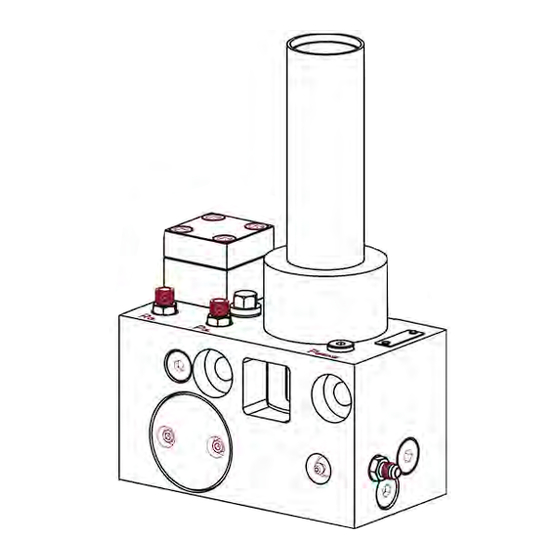
GREASE PUMP ASSEMBLY G015 SPECIFICATIONS GREASE OUTLET PORT GREASE FITTING INLET (HYDRAULIC) PORT RETURN (HYDRAULIC) PORT THROTTLE MOUNTING HOLE GREASE PUMP CARTRIDGE GREASE CARTRIDGE ECCENTRIC SHAFT FILTER/ORIFICE ASSEMBLY HYDRAULIC MOTOR MAIN HOUSING G025 SPECIFICATIONS GREASE OUTLET PORT GREASE FITTING INLET (HYDRAULIC) PORT... -
Page 7: Technical Data
GREASE PUMP ASSEMBLY TECHNICAL DATA HYDRAULIC MOTOR G015 G025 HYDRAULIC FLOW (maximum) .53 gpm (2 lpm) .53 gpm (2 lpm) WORKING PRESSURE 1300 - 3625 psi 1300 - 3625 psi (90 - 250 bar) (90 - 250 bar) MAXIMUM RETURN PRESSURE... -
Page 8: G015 Mounting Specifications
GREASE PUMP ASSEMBLY G015 MOUNTING SPECIFICATIONS G025 MOUNTING SPECIFICATIONS - 7 -... -
Page 9: General Description
GENERAL DESCRIPTION The G015 hydraulically actuated grease pump is used to lubricate the 500 to 2000 ft. lb. class NPK hydraulic hammers. Due to its compact design, it can be mounted directly to the hammer bracket. The NPK hammer mounted auto lube system is connected to the hydraulic system of... - Page 10 GENERAL DESCRIPTION The hydraulic motor (a58) drives a worm shaft (a55), which turns a gear/eccentric unit (a26). As the gear/eccentric unit revolves, it strokes the delivery plunger (a27), which is part of the pumping element (a11). The stroking of the delivery plunger creates suction and delivery of the lubricant.
- Page 11 GENERAL DESCRIPTION The G025 hydraulically actuated grease pump is used to lubricate the 2,500 to 15,000 ft. lb. class NPK hydraulic hammers. Due to its compact design, it can be mounted directly to the hammer upper support block. The NPK hammer mounted auto lube system is connected to the hydraulic system of...
- Page 12 GENERAL DESCRIPTION The hydraulic motor (a58) drives a worm shaft (a55), which turns a gear/eccentric unit (a26). As the gear/eccentric unit revolves, it strokes the delivery plunger (a27), which is part of the pumping element (a11). The stroking of the delivery plunger creates suction and delivery of the lubricant.
- Page 13 GENERAL DESCRIPTION To make sure the pump unit is functioning, the unit has a visible eccentric shaft (a56) which rotates during operation. In the case of wear of the pumping element (grease pump cartridge), the grease comes out of the lateral relief hole (156). If there is failure of the hydraulic system or the Auto Lube pump, a grease fitting (30) is integrated into the unit for manual greasing.
-
Page 14: Functional Description
The pressure line (6) to the hammer is connected to the pressure port P (126) of the NPK Auto Lube pump via a tap in connection on the hammer top bracket. The oil is then routed through a filter (a60) with an orifice (a61) to the hydraulic motor (a58), which ensures continuous drive. -
Page 15: G025
The pressure line (6) to the hammer is connected to the pressure port P (126) of the NPK Auto Lube pump via a tap in connection on the hammer top bracket. The oil is then routed through a filter (a60) with an orifice (a61) to the hydraulic motor (a58), which ensures continuous drive. -
Page 16: Preparation
Remove one part at a time from the box and check off on the NPK parts list. All parts are marked with an NPK part number and balloon item number for ease of identification. -
Page 17: Installation Procedures
INSTALLATION PROCEDURES ORING FACE SEAL FITTING (ORFS) INSTALLATION TIPS Check oring, face of fitting, and tube or hose end for damage and replace if necessary. (RR1) shows a GOOD oring, (RR2) shows a NICKED oring, (RR3) shows a BENT oring, (RR4) shows a CUT oring. -
Page 18: Hose Installation Tips
INSTALLATION PROCEDURES HOSE INSTALLATION TIPS Connect the larger diameter hoses first. Larger hoses are more difficult to bend and maneuver, while the smaller lines are usually more flexible and easier to install. Do not twist (102) the hoses during installation. Pressure applied to a twisted hose can result in premature hose failure or loose connections. -
Page 19: Installation Instructions
INSTALLATION INSTRUCTIONS G015 For NPK 500 to 1300 ft. lb. class hammers (with fixed hammer port connections). 1. The grease pump should be mounted with the grease cartridge (a54) in the vertical position (facing up), with the hammer assembly (DR) horizontal position (as shown). - Page 20 INSTALLATION INSTRUCTIONS G015 For NPK 500 to 1300 ft. lb. class hammers (with fixed hammer port connections). 4. Weld the mounting plate (a28) and drill the access hole in the hammer bracket according to the “Bracket Modification” instructions supplied by NPK.
- Page 21 INSTALLATION INSTRUCTIONS G015 For NPK 500 to 1300 ft. lb. class hammers (with fixed hammer port connections). 6. Install the straight adapter fitting (f1) into the hammer grease port (26). NOTE: The grease fitting (30) is for manual greasing. DO NOT install the above fitting into the hammer’s air connection port (17).
- Page 22 INSTALLATION INSTRUCTIONS G015 For NPK 500 to 1300 ft. lb. class hammers (with fixed hammer port connections). 10. Install the cover plate (YY) over the grease pump assembly (FZ). the four hex head cap screws (AF2) secure cover pump mounting plate.
-
Page 23: For Npk 500 To 1300 Ft. Lb. Class Hammers (With Swivel Hammer Port Connections)
INSTALLATION INSTRUCTIONS G015 For NPK 500 to 1300 ft. lb. class hammers (with swivel hammer port connections). 1. The grease pump should be mounted with the grease cartridge (a54) in the vertical position (facing up), with the hammer assembly (DR) horizontal position (as shown). - Page 24 INSTALLATION INSTRUCTIONS G015 For NPK 500 to 1300 ft. lb. class hammers (with swivel hammer port connections). 4. Weld the mounting plate (a28) and drill the access hole in the hammer bracket according to the “Bracket Modification” instructions supplied by NPK.
- Page 25 INSTALLATION INSTRUCTIONS G015 For NPK 500 to 1300 ft. lb. class hammers (with swivel hammer port connections). 6. Install the supplied straight adapter fitting (f1) or elbow fitting (CF) into the hammer grease port (26). NOTE: The grease fitting (30) is for manual greasing.
-
Page 26: For Npk 2000 Ft. Lb. Class Hammers (With Top Brackets That Include Joint Fittings)
INSTALLATION INSTRUCTIONS G015 For NPK 2000 ft. lb. class hammers (with top brackets that include joint fittings). 1. The grease pump should be mounted so that the grease cartridge (a54) is in the vertical position when the hammer is in operation. It must be ensured... - Page 27 INSTALLATION INSTRUCTIONS G015 For NPK 2000 ft. lb. class hammers (with top brackets that include joint fittings). 4. Weld the mounting blocks (a87), using mounting bracket G015-2045 (a28) to check alignment, onto the hammer bracket according to the “Bracket Modification” instructions supplied by NPK.
- Page 28 INSTALLATION INSTRUCTIONS G015 For NPK 2000 ft. lb. class hammers (with top brackets that include joint fittings). 5.1. For units with SAE style joint fittings. a. Disconnect the hammer hoses (m5 and m6) from the top bracket joint fittings (m18a, m18b).
- Page 29 INSTALLATION INSTRUCTIONS G015 For NPK 2000 ft. lb. class hammers (with top brackets that include joint fittings). e. Install hose line (a63). Route hose from pressure side joint fitting (m18a), through top bracket burnout, to port labeled “P ” on the grease pump (FZ).
- Page 30 INSTALLATION INSTRUCTIONS G015 For NPK 2000 ft. lb. class hammers (with top brackets that include joint fittings). Install special elbows (a88a and a88b) into the joint fittings (a18a and a18b). Reconnect the hammer hoses (m5 and m6). d. Install hydraulic hose (a64). Route hose from return side joint fitting (m18b), through top bracket burnout, to port labeled “R...
- Page 31 INSTALLATION INSTRUCTIONS G015 For NPK 2000 ft. lb. class hammers (with top brackets that include joint fittings). 6. Install the supplied straight adapter fitting (f1) into the hammer grease port (26). DO NOT install the above fitting into the hammer’s air connection port (17). It is used in underwater applications.
- Page 32 INSTALLATION INSTRUCTIONS G015 For NPK 2000 ft. lb. class hammers (with top brackets that include joint fittings). 7. Route the straight end of the pressure hose (a63) from port “P ” on the grease pump assembly (FZ) through the inside hammer and top bracket burnouts, to the pressure side joint fitting (m18a) adapter tee.
-
Page 33: G025
INSTALLATION INSTRUCTIONS G025 For NPK 2,500 to 15,000 ft. lb. class hammers 1. The grease pump should be mounted so that the grease cartridge (a54) in the vertical position when the hammer is in operation. It must be ensured that... - Page 34 INSTALLATION INSTRUCTIONS G025 For NPK 2,500 to 15,000 ft. lb. class hammers 4. Remove the pump assembly and finish welding the mounting plate. (Weld as much around the perimeter as possible.) Bolt the grease pump (FZ) to its mounting plate using the...
- Page 35 INSTALLATION INSTRUCTIONS G025 For NPK 2,500 to 15,000 ft. lb. class hammers 6. Pre-fill the grease line (29) before installing (see the grease line pre-filling section of this manual, pages 38 and 39). Route the hose under the hammer swivel fitting and connect to the grease outlet port (18) on the side of the grease pump assembly (FZ).
- Page 36 INSTALLATION INSTRUCTIONS G025 For NPK 2,500 to 15,000 ft. lb. class hammers c. Install straight fitting (g19) into the special adapter fitting. Use the port that closely faces the center of the top bracket, which will allow for the best hose routing.
- Page 37 INSTALLATION INSTRUCTIONS G025 For NPK 2,500 to 15,000 ft. lb. class hammers b. Install straight fittings (g19) into the special elbows (a88). c. Install special elbows (a88a and a88b) into the joint fittings (a18a and a18b). Reconnect the hammer hoses (m5 and m6).
- Page 38 Install hydraulic hose (a63). Route hose from pressure side joint fitting (m18a), through top bracket burnout, to port labeled “P ” on the grease pump. 8. Wrap hydraulic lines (a63 and a64) together using a protective hose covering (supplied by NPK). For best fit, cut to appropriate length. - 37 -...
-
Page 39: Before Start-Up
BEFORE START-UP AUTO LUBE GREASE LINE PRE-FILLING It is mandatory that the supply line from the Auto Lube main pump to the connection on the hammer is primed with grease before it is used. Failure to do this will result in no grease being administered to the hammer tool for a period of time. - Page 40 BEFORE START-UP PRIMING THE GREASE LINE 6. Pump grease through the pump to the grease line (29) until a steady stream of grease (28) is realized at the opposite (hammer) end. 6a. It is also possible to purge the grease line to the hammer by disconnecting it at the hammer then pumping grease through the grease fitting provided on...
-
Page 41: Underwater Use
DO NOT attempt to change a grease cartridge while the unit is underwater. AUTO LUBE TROUBLESHOOTING If the NPK Auto lube unit is not pumping grease correctly, the following steps may be taken to diagnose and correct the problem. PROBLEM... -
Page 42: Grease Cartridges
GREASE CARTRIDGES NPK offers only one cartridge (which is used on both the G015 and G025). It is referred to as a type S. The NPK part number for this cartridge is G025-1050. NOTE: If you are using any of the other types (F or L) of cartridges offered with these units, contact NPK @ 1-800-225-4379. -
Page 43: Changing The Cartridge Adapter (G025 Only)
GREASE CARTRIDGES CHANGING THE CARTRIDGE ADAPTER (G025 ONLY) DISASSEMBLY 1. To remove the adapter (a53) from the pump housing (a59), remove the four socket head cap screws (OO) found on the bottom of the pump housing using a 4mm hex key wrench. 2. -
Page 44: Changing The Flat Seal (G015)
GREASE CARTRIDGES CHANGING THE FLAT SEAL (G015) 1. Remove the grease cartridge. 2. Using a pick, remove the flat seal (a65) and o-ring (RR). 3. Inspect the lubricant passage (176) for contamination. 4. Apply a light coat of grease to the new flat seal and o-ring, then install. -
Page 45: Changing The Grease Cartridge (G015)
GREASE CARTRIDGES CHANGING THE GREASE CARTRIDGE (G015) 1. Remove the old grease cartridge. 2. Before installing the grease cartridge (a54), make sure the flat seal (a65) is present and not damaged. If the flat seal is missing or damaged, see “CHANGING THE FLAT SEAL”. -
Page 46: Changing The Grease Cartridge (G025)
GREASE CARTRIDGES CHANGING THE GREASE CARTRIDGE (G025) 1. Remove the old grease cartridge. 2. Before installing the grease cartridge, make sure the flat seal (a65) is present and not damaged. If the flat seal is missing or damaged, see “CHANGING THE FLAT SEAL”... -
Page 47: Grease Cartridge Refilling
GREASE CARTRIDGES GREASE CARTRIDGE REFILLING 1. Screw cartridge fill adapter (t70), NPK part number G025-8055 onto the empty grease cartridge (a54e). 2. Push nozzle (t69) of the grease gun into the cartridge re-fill adapter (t70). 3. Pump grease into empty cartridge until the follower piston is approximately 3/8”... -
Page 48: Replacement Of The Filter And Diaphragm
REPLACEMENT OF THE FILTER AND DIAPHRAGM For replacement of the filter and diaphragm, you must first remove the plug (AS). Then you can remove the filter thrust piece (a67), oring (RR), sealing ring (a69) and strainer (a60). Use a slotted screwdriver (t22) to remove the diaphragm (a61). NOTE: Upon re-installation, make sure that the sealing edge of the diaphragm is not damaged. -
Page 49: Replacement Of The (Lubricant) Relief Valve
REPLACEMENT OF THE (LUBRICANT) RELIEF VALVE (G025 ONLY) To protect the circulation of the lubricant grease), pump includes integrated pressure relief valve. This opens at a pressure of 4060 psi (280 bar). To replace the pressure relief valve, you first have to remove the plug (AS) using a hex key wrench (t25). -
Page 50: Pump Cartridge Test Procedure
TOOLS REQUIRED: 6 mm Hex Key Wrench Electric or air powered drill Drive Shaft – NPK Part Number G025-5075 PROCEDURE: 1. Remove hydraulic motor (a58) from the pump assembly (FZ). 2. Install a grease cartridge. (Make sure flat seal is in place.) -
Page 51: Replacement Of The Pump Cartridge
REPLACEMENT OF THE PUMP CARTRIDGE When removing the pump cartridge, make sure the hydraulic and lubricant systems are depressurized. To be able to remove the pump cartridge from the pump housing, you must remove the lock screw (a70) using an 8mm hex key wrench. To pull out the pumping element, use a 12mm bolt (OO). -
Page 52: Throttle Adjustment
THROTTLE ADJUSTMENT ADJUSTMENT OF FLOW TO THE HYDRAULIC MOTOR To adjust the hydraulic motor’s flow rate, you must first depressurize the hydraulic system. You will then need to remove the plug (AS) and the flat seal (a65) covering the throttle (a5). You can then adjust the throttle using a slotted screwdriver (t22). By turning the throttle counterclockwise, you will increase the flow rate to the hydraulic motor, thus increasing the lubricant flow rate. - Page 53 THROTTLE ADJUSTMENT ADJUSTMENT OF FLOW TO THE HYDRAULIC MOTOR The following diagram shows the guide values for adjustment of the throttle. Before adjustment, screw the throttle clockwise in until it stops (do not jam it in). By turning the throttle counterclockwise, you can adjust to the desired delivery rate. gr01 Eccentric revolutions per minute gr02...
-
Page 54: Keywords For Common G015 Auto Lube Components
KEYWORDS FOR COMMON G015 AUTO LUBE COMPONENTS GREASE FITTING FLAT SEAL THROTTLE FILTER THRUST PIECE PUMP CARTRIDGE SEAL RING ECCENTRIC PLUG GREASE CARTRIDGE ADAPTER FITTING ECCENTRIC SHAFT ORSm x SAEm FILTER/ORIFICE CHECK VALVE ASSEMBLY JICm x SAEm HYDRAULIC MOTOR CHECK VALVE... -
Page 55: Keywords For Common G025 Auto Lube Components
KEYWORDS FOR COMMON G025 AUTO LUBE COMPONENTS GREASE FITTING FLAT SEAL THROTTLE FILTER THRUST PIECE PUMP CARTRIDGE SEAL RING ECCENTRIC PLUG CARTRIDGE ADAPTER bs25 RELIEF VALVE GREASE CARTRIDGE ADAPTER FITTING ECCENTRIC SHAFT ORSm x SAEm FILTER/ORIFICE CHECK VALVE ASSEMBLY JICm x SAEm HYDRAULIC MOTOR CHECK VALVE MAIN HOUSING... -
Page 56: Keywords For Common Hammer Mounted Auto Lube Hydraulic Motor Components
KEYWORDS FOR COMMON HAMMER MOUNTED AUTO LUBE HYDRAULIC MOTOR COMPONENTS DRIVE GEAR DRIVEN GEAR SHAFT SEAL WASHER hm16 MOTOR END CAP hm23 GEAR HOUSING hm28 BUSHING DOWEL PIN CAP SCREW O-RING DRIVE SHAFT - 55 -... -
Page 57: Warranty Statements
WARRANTY STATEMENTS - 56 -... - Page 58 WARRANTY STATEMENTS - 57 -...
- Page 59 WARRANTY STATEMENTS - 58 -...
- Page 60 © Copyright 2019 NPK Construction Equipment, Inc. www.npkce.com G025-9600g Hammer Mounted Auto Lube System 11-19...
Need help?
Do you have a question about the G015 and is the answer not in the manual?
Questions and answers