Table of Contents
Advertisement
Specifications*
General
Power Supply
Tone Controls
Current Consumption
Maximum Power Output
Suitable Speaker Impedance
Pre-Amp Output Voltage
Output Impedance
FM Stereo Radio
Frequency Range
Usable Sensitivity
AM Radio
Frequency Range
LW Radio
Frequency Range
DC 12V (11V - 16V),
Test Voltage 14.4V
Negative Ground
Bass ; ±12dB at 100Hz
Treble ; ±12dB at 10kHz
Less than 2.2A (CD play mode,
0.5W×4ch)
50W×4ch (at 1kHz, Vol. Max.)
4-8Ω
2.5V (CD play mode; 1kHz, 0dB)
200Ω
87.5 - 108MHz
11.0dBf (1.25µV, 75Ω)
531 - 1,602kHz
153 - 279kHz
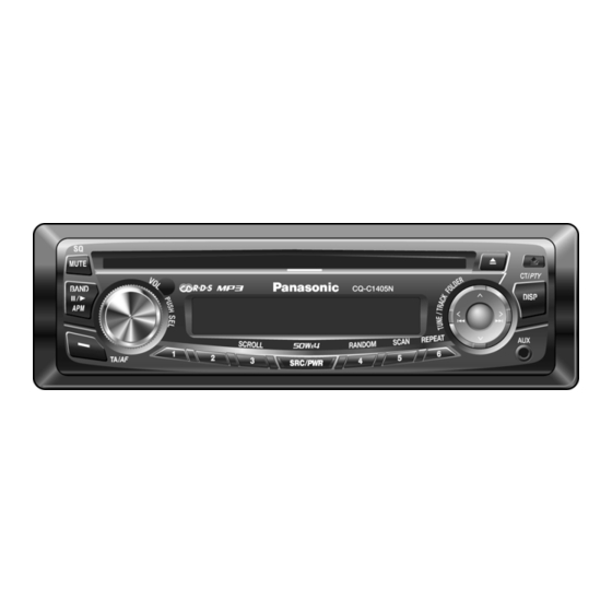
AUTOMOTIVE AFTERMARKET
CQ-C1405N
Removable Front Panel CD Player /
Receiver
Usable Sensitivity
RDS
RDS Senstivity
CD Player
Sampling Frequency
Pick-Up Type
Light Source
Wavelength
Frequency Response
Signal to Noise Ratio
Dimensions**
Weight**
* Specifications and the design are subject to possible modification
without notice due to improvements.
** Dimensions and Weight shown are approximate.
© 2006 Matsushita Electric Industrial Co., Ltd. All
rights
reserved.
distribution is a violation of law.
Order No. ACED061206C8
28dB/µV (25µV, S/N 20dB)
22dB/µV
8 times oversampling
Astigma 3-beam
Semiconductor Laser
780nm
20Hz to 20,000Hz (±1dB)
96dB
178×50×155mm
1.4kg
Unauthorized
copying
and
Advertisement
Table of Contents

Related Manuals for Panasonic CQ-C1415N


Summarization of Contents
Product Specifications
General Specifications
Details on power supply, tone controls, current consumption, maximum output, and impedance.
Radio & Audio Performance
Tuning ranges, sensitivity, RDS data, frequency response, and signal-to-noise ratio.
Physical Dimensions & Weight
Unit dimensions and weight for installation and handling.
Safety Information
Service Warning
Advisory for experienced technicians regarding service procedures.
Important Safety Notice
Critical parts, shock/fire prevention, and design modification warnings.
Product Features
Key Features List
Lists remote control, presets, digital servo, and removable faceplate.
Laser Safety Precautions
Laser Handling Guidelines
Safety guidelines for handling laser products to avoid exposure.
Maintenance and Repair
Fuse Replacement Guide
Instructions for replacing fuses with correct rating.
Maintenance and Technical Notes
Cleaning and Care Instructions
Guidance on routine exterior cleaning using a dry, soft cloth.
Technical Notes
Notes on radio block alignment and CD deck servo circuit operation.
Physical Dimensions
Unit Size Diagram
Visual representation of unit dimensions with measurements.
Wiring Connection Diagram
System Wiring Overview
Illustrates electrical connections between main PCB, display, and servo blocks.
System Block Diagram
Functional Block Overview
Shows functional blocks like TUNER, CD DSP, u-COM, and POWER AMP.
Terminal Descriptions: Main Block
IC601 Pinout
Detailed pinout and function for the main block IC601.
IC501 Pinout
Detailed pinout and function for the main block IC501.
IC401 Pinout
Detailed pinout and function for the main block IC401.
IC701 Pinout
Detailed pinout and function for the main block IC701.
Terminal Descriptions: Display Block
IC901 Pinout
Detailed pinout and function for the display block IC901.
IC and Block Diagrams
Main Block IC Diagrams
Package and IC block diagrams for Main Block ICs (IC271, PA51).
Microcontroller IC Diagrams
Block diagrams for microcontroller ICs (IC401, IC701).
Audio Processor IC Diagram
Block diagram for audio processor IC251.
Tuner IC Diagram
Block diagram for tuner IC551.
Replacement Parts Catalog
ICs, Transistors, and Diodes
Lists of ICs, transistors, and diodes with part numbers.
Capacitors
List of capacitors with part numbers and types.
More Capacitors
Continued list of capacitors with part numbers and types.
Resistors
List of resistors with part numbers and values.
Switches, Connectors, Accessories
List of switches, connectors, accessories, and installation parts.
Mechanical Parts Catalog
Miscellaneous Mechanical Components
List of various mechanical parts including screws, holders, buttons, and panels.
Sub-Assemblies
List of major sub-assemblies like Deck Assy, PCB Assy, and Holders.
Exploded View: Unit Assembly
Unit Assembly Breakdown
Visual diagram showing the exploded view of the entire unit.
CD Player Mechanical Parts Catalog
Mechanical Components
List of mechanical parts for the CD player mechanism.
CD Player Sub-Assemblies
List of mechanical sub-assemblies for the CD player.
Exploded View: CD Deck Assembly
CD Deck Assembly Diagram
Visual diagram showing the exploded view of the CD deck mechanism.
Wiring Diagrams Overview
Main PCB Wiring (Top View)
Wiring diagram for the main PCB (top view).
Main PCB Wiring (Bottom View)
Wiring diagram for the main PCB (bottom view).
Display PCB Wiring
Wiring diagrams for the display PCB (top and bottom views).
CD Servo Block Wiring
Wiring diagram for the CD servo block.
Schematic Diagrams Overview
Main Block Schematic
Detailed schematic diagram for the main block of the unit.
Display Block Schematic
Detailed schematic diagram for the display block of the unit.
CD Servo Block Schematic
Detailed schematic diagram for the CD servo block.
Main Block (Left Side) Schematic
Schematic diagram for the left side of the main block.
Main Block (Right Side) Schematic
Schematic diagram for the right side of the main block.
Need help?
Do you have a question about the CQ-C1415N and is the answer not in the manual?
Questions and answers