
Related Manuals for ELSA 3L-AP

Summarization of Contents
CHAPTER 1 QUICK GUIDE TO INSTALLATION
1.1 INTRODUCTION
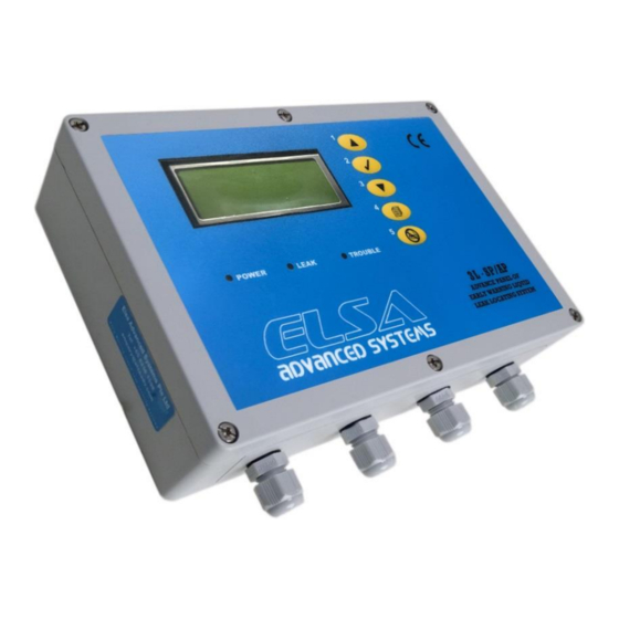
Overview of the 3L-SP/AP panel, its response time, and mounting.
1.2 PANEL WIRING & CONNECTIONS
Details on panel wiring, pin assignments, and cable connections.
1.3 TESTING PROCEDURE
Step-by-step guide for performing leak tests.
1.4 FALSE ALARM TROUBLESHOOTING
Common causes and solutions for false alarms.
CHAPTER 2 PRODUCT SPECIFICATION
2.1 GENERAL FEATURES
Key features of the 3L-SP/AP panel including cable length, display, and relays.
2.2 ENVIRONMENTAL RATINGS
Operating and storage temperature, and humidity specifications.
2.3 POWER REQUIREMENTS
Power supply voltage, optional input, and consumption.
2.7 COMPLIANCE TO INTERNATIONAL STANDARDS
EMC emission and immunity standards compliance.
CHAPTER 3 PRODUCT SELECTION GUIDE
3.1 3L-SP/AP PANEL WITH MULTI ZONES
How to connect multiple zones using jumper cables.
3.2 3L-SP/AP PANEL FAIL SAFE LOOP BACK CONNECTION DETAILS
Details on fail-safe loop back cable connection.
3.3 3L-SP/AP PANEL WITH EXTERNAL RELAY AND SOLENOID VALVE
Wiring diagram for connecting external relays and solenoid valves.
3.7 RS485 MODBUS COMMUNICATION PROTOCOL
Details on setting up RS485 Modbus communication.
CHAPTER 4 COMMUNICATION PROTOCOL: MODBUS PARAMETERS OF 3L-SP/AP
Serial Port Configuration
Serial port settings: 9600 B, 8 data bits, 1 stop bit, no parity.
Communication Protocol
Specifies MODBUS functions 3 or 4 for communication.
Slave (Control Panel) Numbering
How to set the slave number in the panel's configuration menu.
Modbus Register Addresses
Table detailing Modbus register addresses for alarm types and locations.
CHAPTER 5 MAINTENANCE SERVICE PROCEDURE
5.1 MAINTENANCE SERVICE
Recommendation for quarterly system performance checks by authorized personnel.
5.2 MANUFACTURING PRODUCT INFORMATION AND CONTACT
Contact details and address for ELSA Advanced Systems Pte. Ltd.
5.3 TESTING & COMMISSIONING CHECK LIST
A checklist for testing and commissioning the system.
CHAPTER 6 TROUBLESHOOTING GUIDE
6.1 TROUBLESHOOTING
General troubleshooting tips for the panel and leak detection.
6.2 TROUBLESHOOTING FALSE ALARMS
Diagnosing and resolving false alarms post-installation.
6.2.1 CONTINUOUS FALSE ALARM SCENARIOS
Scenarios causing continuous false alarms (e.g., chemical stains).
6.2.2 INTERMITTENT FALSE ALARM SCENARIOS
Scenarios causing intermittent false alarms (e.g., contact with metal, improper laying).
Need help?
Do you have a question about the 3L-AP and is the answer not in the manual?
Questions and answers