Sign In
Upload
Download
Table of Contents
Contents
Add to my manuals
Delete from my manuals
Share
URL of this page:
HTML Link:
Bookmark this page
Add
Manual will be automatically added to "My Manuals"
Print this page
×
Bookmark added
×
Added to my manuals
Manuals
Brands
ELSA Manuals
Control Panel
3L-SP
User manual
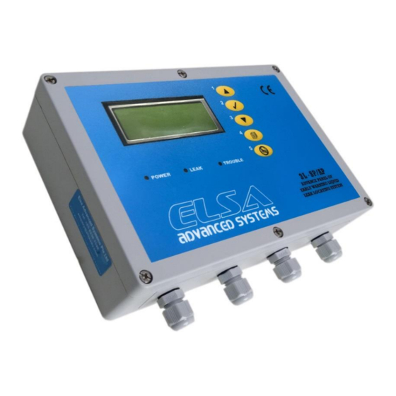
ELSA 3L-SP User Manual
Leak control panel with alarm and lcd display for liquid leakage locating & detection system
Hide thumbs
1
Table Of Contents
2
3
4
5
6
7
8
9
10
11
12
13
14
15
16
17
18
19
20
21
22
23
24
25
26
27
28
29
30
31
32
33
page
of
33
Go
/
33
Contents
Table of Contents
Troubleshooting
Bookmarks
Table of Contents
Table of Contents
Chapter 1 Quick Guide to Installation
Introduction
Sp/Ap Panel Wiring Details
Sp/Ap Panel Pin Number Details
Cable Connection Details
Sp/Ap Control Panel - Power on
Testing Procedure
False Alarm Troubleshooting
Tag or Label for Sensing Cable
Hold down Clip for Sensing Cable
Sp/Ap Panel Mounting Hole Dimensions
Chapter 2 Product Specification
General Features
Environmental Ratings
Power Requirements
Power Relays Switching Characteristics
Supervising Channel
Serial Communication Interface
Compliance to International Standards
Chapter 3 Product Selection Guide
Sp/Ap Panel with Multi Zones
Sp/Ap Panel Fail Safe Loop Back Connection Details
Sp/Ap Panel with External Relay and Solenoid Valve
T-Joint Connection Details
Ds with Multi Zone Connection Details
Sp with 3L-Sp/Ap Connection Details
Rs485 Modbus Communication Protocol
Chapter 4 Communication Protocol: Modbus Parameters of 3L-Sp/Ap
Chapter 5 Maintenance Service Procedure
Maintenance Service
Manufacturing Product Information and Contact
Testing & Commissioning Check List
Chapter 6 Troubleshooting Guide
Troubleshooting
Troubleshooting False Alarms after Installation
Continuous False Alarm - Possible Scenarios
Intermittent False Alarm - Possible Scenarios
Chapter 7 Applications
Advertisement
Quick Links
1
Sp/Ap Panel Wiring Details
2
Cable Connection Details
3
Testing Procedure
4
False Alarm Troubleshooting
5
Rs485 Modbus Communication Protocol
6
Testing & Commissioning Check List
7
Troubleshooting
Download this manual
3L-SP/AP
Leak Control Panel with
Alarm and LCD Display
For
Liquid Leakage
Locating & Detection System
User Guide
(2017 Rev 1)
1
Table of
Contents
Previous
Page
Next
Page
1
2
3
4
5
Advertisement
Table of Contents
Troubleshooting
FALSE ALARM TROUBLESHOOTING
8
CHAPTER 6 TROUBLESHOOTING GUIDE
25
TROUBLESHOOTING FALSE ALARMS AFTER INSTALLATION
26
Need help?
Do you have a question about the 3L-SP and is the answer not in the manual?
Ask a question
Questions and answers
Related Manuals for ELSA 3L-SP
Control Panel ELSA 3L-AP User Manual
Leak control panel with alarm and lcd display for liquid leakage locating & detection system (33 pages)
This manual is also suitable for:
3l-ap
Table of Contents
Save PDF
Print
Rename the bookmark
Delete bookmark?
Delete from my manuals?
Login
Sign In
OR
Sign in with Facebook
Sign in with Google
Upload manual
Upload from disk
Upload from URL


Need help?
Do you have a question about the 3L-SP and is the answer not in the manual?
Questions and answers