Table of Contents
Advertisement
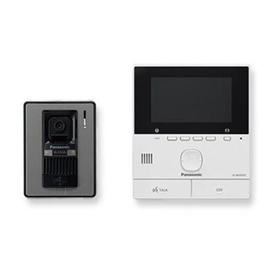
Video Intercom System
VL-SVN511BX
Model No.
VL-MVN511BX
VL-V522LCE
VL-RLY1
VL-PS241
VL-SVN511CX
Model No.
VL-SVN511CX1
Model No.
VL-MVN511BX
VL-V522LCE
VL-RLY1
VL-PS241
(BX: for Asia, Middle Near East and Africa)
(CX: for Middle East and Hong Kong)
(CX1: for UAE)
© Panasonic Corporation 2019
Unauthorized copying and distribution is a violation
of law.
ORDER NO. KMA1511067CE
[Version 2.0]
Advertisement
Table of Contents

Related Manuals for Panasonic VL-SVN511CX


Summarization of Contents
Safety Precautions and Warnings
General Safety Precautions
General safety guidelines for servicing, including unplugging power and using recommended parts.
Service Technician Safety
Precautions for technicians regarding product modification and handling of static-sensitive components.
Lead Free Solder Information
Information and cautions regarding the use of lead-free solder, including melting points and handling.
Repair and Discarding Notes
Guidelines for insulation resistance tests, discarding PCBs, and handling user data during repairs.
Product Specifications
Main Monitor Station Specifications
Details specifications for the VL-MVN511 main monitor station, including power, dimensions, and display.
Power Supply Unit Specifications
Specifications for the VL-PS241 power supply unit, including input/output voltages and dimensions.
Relay Box Specifications
Specifications for the VL-RLY1 relay box, including power source, dimensions, and installation.
Door Station Specifications
Specifications for the VL-V522LCE door station, including viewing angle and illumination requirements.
Technical Descriptions
Video Intercom System Overview
Explains the concept of video intercoms and details system blocks like block diagrams, sensors, and FM modulation.
Main Monitor Station IC Operations
Details the function of ICs in the main monitor station, power board, and external interfaces.
Door Station and Relay Box Sections
Describes IC operations for the door station and provides the relay box diagram.
Troubleshooting Guide
Door Station Operation Check
Flowchart to diagnose and resolve issues with the door station's operation.
Main Monitor Station Operation Check
Flowchart to diagnose and resolve issues with the main monitor station's operation.
Main Monitor Power Supply Defects
Troubleshooting flowchart for power supply failures on the main monitor station.
WiFi Communication Defects
Troubleshooting flowchart for issues related to WiFi connectivity on the main monitor.
Video Recording Defects
Troubleshooting flowchart for problems with the main monitor's video recording function.
Communication Defects Between Stations
Flowcharts for diagnosing communication failures between main monitor, door station, and PBX.
Electric Lock and External Input Defects
Troubleshooting flowcharts for electric lock operation and external input issues.
Error Messages and Solutions
Lists common error messages displayed by the main monitor and their corresponding causes and solutions.
Disassembly and Assembly Instructions
Main Monitor Station Disassembly
Step-by-step instructions for disassembling the main monitor station, including removing the DC cable and cabinet.
Door Station Disassembly
Procedures for disassembling the door station, including removing the mounting base, main board, and camera.
Power Supply Unit and Relay Box Disassembly
Instructions for disassembling the power supply unit and the relay box.
Measurements and Adjustments
Main Monitor Station Measurement Procedures
Details connections and procedures for measuring and adjusting the main monitor station.
Post-IC Replacement Procedures
Steps for initializing and adjusting the system after IC replacement, including software setup.
Factory Mode and Setup Operations
Instructions for entering factory mode, performing factory setup, and adjusting white balance.
Schematic Diagrams and PCB Layouts
Schematic Diagrams by Unit
Provides schematic diagrams for the main monitor, door station, power supply unit, and relay box.
Printed Circuit Board Layouts
Shows component layouts and bottom views for the main monitor, door station, power supply, and relay box PCBs.
Exploded Views and Replacement Parts
Exploded Views of System Components
Illustrates exploded views of the main monitor, door station, power supply, relay box, and accessories.
Replacement Parts Lists by Unit
Comprehensive lists of replacement parts for all system components, including cabinet, PCB, accessories, and tools.
Need help?
Do you have a question about the VL-SVN511CX and is the answer not in the manual?
Questions and answers