
Related Manuals for AGRO-MASZ POV3


Summary of Contents for AGRO-MASZ POV3
- Page 1 _________________________________ Instruction manual Warranty certificate Parts catalogue ROTARY PLOUGH POV, POVR, POVH AGRO-MASZ Paweł Nowak Strzelce Małe 78 97-515 Masłowice Tel. +48 44 787 49 24 Fax. +48 44 787 12 02...
- Page 2 Address: agro-masz.eu Language version: ENGLISH Document No: IO.PO.17.1 Created: JANUARY 2017 Copying and making excerpts only on written consent of AGRO-MASZ Paweł Nowak.
-
Page 3: Dear Customers
In case of its loss or damage, a new copy must be purchased. The new instruction manual can be ordered from the dealer of AGRO-MASZ- brand the machines or directly from the manufacture. -
Page 4: Ec Declaration Of Conformity For The Machine
EC DECLARATION OF CONFORMITY FOR THE MACHINE Manufacturer AGRO-MASZ Paweł Nowak Strzelce Małe 78 97-515 Masłowice Machine Name: Rotary plough Type / Model: ………………… Factory number: ………………… Year of manufacture: ………………… Application: bed free ploughing of medium and large depth. -
Page 5: The Machine Identification
THE MACHINE IDENTIFICATION THE MACHINE IDENTIFICATION 2.1. Name Mounted rotary plough. 2.2. Model symbol POV3 – Rotary plough, 3-furrow POV4 – Rotary plough, 4-furrow POV5 – Rotary plough, 5-furrow Identification data can be found on data plate attached to the machine's frame by the three-point linkage. -
Page 6: Manufacturer Data
Tel./Fax…………………………………….. NOTE! Remember the name and symbol of your machine. Always use this name and symbol in contact with the seller or the manufacturer. 2.4. Manufacturer data AGRO-MASZ Paweł Nowak Spare parts Export Strzelce Małe 78 Tel. + 48 603 728 099 Tel. -
Page 7: Table Of Contents
TABLE OF CONTENTS III. TABLE OF CONTENTS ! ........................... 3 USTOMERS I. EC DECLARATION OF CONFORMITY FOR THE MACHINE ............4 ..........................4 ANUFACTURER ............................4 ACHINE II. THE MACHINE IDENTIFICATION ....................5 2.1. N ............................. 5 2.2. M ........................5 ODEL SYMBOL 2.3. - Page 8 VI. GENERAL INFORMATION ....................26 6.1. T .................... 26 ECHNICAL DATA FOR PLOUGHS 6.2. C ......................29 ONSTRUCTION OF PLOUGH 6.3. C ....................... 29 ONSTRUCTIONAL CHANGES VII. MAINTENANCE AND SERVICE ..................... 30 7.1. P .............. 30 REPARATION OF THE TRACTOR TO WORK WITH THE PLOUGH 7.1.1.
- Page 9 9.1. L .......................... 54 UBRICATION 9.2. B ........................56 OLT TIGHTENING 9.3. I ..................57 NSTRUCTIONS FOR PROPER OPERATION 9.4. D ......................60 ETACHMENT OF PLOUGH 9.5. S ..........................61 TORAGE 9.6. R ......................61 EPLACEMENT OF PARTS 9.7. D ....................
-
Page 10: Initial Explanations
4.2. User feedback AGRO-MASZ will be grateful for sending any comments on the use and operation of the machine and on this instruction manual. Instruction manuals are regularly updated, but it is your feedback that enables us to jointly create a user-friendly instruction manual. -
Page 11: Recommendations And Descriptions
INITIAL EXPLANATIONS 4.3. Recommendations and descriptions The recommendations, referred to as: WARNING, NOTE, REMEMBER, are used in order to underline the importance of information. WARNING! This indicates the possibility of danger, which if not avoided, can lead to cutting or heavier injuries to the personnel operating the machine. NOTE! This is used when there is the risk of damage to the machine. -
Page 12: Safety Notes
SAFETY SAFETY NOTES REMEMBER! Before operation and use of the (tractor + plough) assembly, get acquainted with this instruction manual, the construction of the plough and its sub-assemblies, their functions, ranges and adjustment method, paying special attention to information on the work safety. During work it is too late for that! The mentioned safety regulations refer to the plough. - Page 13 SAFETY Do not stand between the tractor and the plough while the engine is working. • • When connecting hoses to tractor's hydraulic system make sure the hydraulic system is depressurized. Check position of control levers for the tractor's hydraulic system. •...
-
Page 14: Warning Pictograms Placed On The Plough
periodically, every 4 years from the date of their manufacture. The date of manufacture, i.e. year and week number, is indicated on hydraulic hoses. Exercise particular care when driving on public roads, observe the relevant • road traffic rules and regulations. For the time of transport on the public roads, install the following on the plough: warning signs painted in white and red stripes, with lamps: front –... - Page 15 SAFETY The below section presents graphically warning signs, shows their location on the machine, explains what type of risk they indicate and the way to keep safety and avoid hazard. Additionally, each sign bears a number, which refers to the number of a warning pictogram included in the parts catalogue, which facilitates identification of a label if damaged.
- Page 16 SAFETY D. Risk of crushing of the body within the three-point linkage operating area! This risk can result in crushing of chest or other part of the body, or even the death of the operator. It is forbidden to stand between the machine and tractor when fixing the machine and starting the lifting device! E.
-
Page 17: Location Of Warning Pictograms On The Machine
SAFETY H. Marking of a place to fasten loading slings! These are suggested places to maintain the safe loading / unloading of the machine and its balance while it is hanging on ropes, belts or chains. Always take the weight of the lifted machine into account! 5.3. -
Page 18: Other Risks
SAFETY 5.4. Other risks In addition to the risks defined in the section 5.2. and presented in the form of warning pictograms placed on the machine, the other risks described by manufacturer in this section can also appear during operation. 5.4.1. -
Page 19: Residual Energy
SAFETY • It is forbidden to lock hydraulic system controls in the tractor. • Before any works on the hydraulic system: Lower the mounted machine, Depressurise the hydraulic system, Turn the tractor's engine off and engage the parking brake, Remove the ignition key. 5.4.3. -
Page 20: Operator's Obligations And Training
SAFETY 5.5. Operator’s obligations and training 5.5.1. Operator’s obligations The operator must: get acquainted with the instruction manual attached to the machine, in • particular become familiar with the safety regulations related to work, repair and maintenance, • take care that the instruction manual is always stored in a place ensuring its maintenance in good condition and to make sure it is always available during work, •... -
Page 21: Risk Zones
SAFETY clothing which do not constrain movements but, a the same time, • are tight to such extent not to be caught by any of the machine's sub-assembly, protective goggles, hearing protectors and breathing protection • mask, if necessary (when strong wind is encountered during operation or the tractor is not provided with a cab). -
Page 22: Residual Risk
5.7.1. Description of residual risk Despite the fact, that the AGRO-MASZ company – the manufacturer of the PO plough takes the responsibility for the design and manufacture, in order to eliminate hazard, certain risk when operating the machine is unavoidable. -
Page 24: Stability Of Tractor - Plough Assembly
SAFETY NOTE! Accident hazards resulting from the existing residual risk appear in case of failure to observe the specified recommendations and guidelines. 5.8. Stability of tractor - plough assembly The tractor-plough assembly can lose its stability due to weight of the mounted machine. - Page 25 SAFETY – tractor's overall weight [kg] �� �� – front axle load of unloaded tractor [kg] �� �� – rear axle load of unloaded tractor [kg] �� �� – weight of front ballast weights [kg] �� �� – weight of machine mounted at rear [kg] ��...
-
Page 26: General Information
GENERAL INFORMATION GENERAL INFORMATION The plough, intended for sale, is delivered assembled by the manufacturer. Plough bodies are equipped with sectional mouldboards, ploughshares with bolted chisel, strips and landsides and skimmers to be mounted above mouldboards for better coverage of plant residues. Mounting of plough body core (frog) to plough beam enables plough body tilt angle adjustment. - Page 27 PARAMETER UNIT OF PLOUGH PLOUGH PLOUGH MEASURE POVR3 POVR4 POVR5 Type mounted mounted mounted Number of bodies - distance between bodies 1000 1000 1000 on frame, - height under frame, semihelicoidal semihelicoidal semihelicoidal - mouldboard type, zone zone zone - ploughshare type, tempered tempered tempered...
- Page 28 PARAMETER UNIT OF PLOUGH PLOUGH PLOUGH MEASURE POVH3 POVH4 POVH5 Type mounted mounted mounted Number of bodies - distance between bodies 1000 1000 1000 on frame, - height under frame, semihelicoidal semihelicoidal semihelicoidal - mouldboard type, zone zone zone - ploughshare type, tempered tempered tempered...
-
Page 29: Construction Of Plough
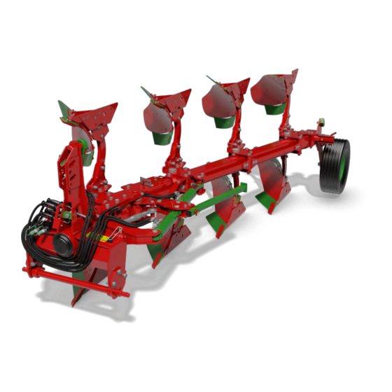
GENERAL INFORMATION 6.2. Construction of plough Overview of POV plough in version with skim coulters. MOULDBOARD SUPPORT FIRMER PLOUGH BEAM MOUNTING CHISEL PLOUGHSHARE BREAST FROG LANDSIDE Construction of a single body. 6.3. Constructional changes Equipment of your machine can slightly differ from equipment provided in figures or in descriptions included in this instruction manual. -
Page 30: Maintenance And Service
OPERATION VII. MAINTENANCE AND SERVICE Before working, it is necessary to carefully get acquainted with the function and construction of the tractor's and plough's parts. 7.1. Preparation of the tractor to work with the plough REMEMBER! In order to make proper adjustments of the below-described sub-assemblies of the tractor, observe the provisions specified in the instruction manual provided by the tractor's manufacturer. -
Page 31: Three-Point Linkage
OPERATION 7.1.3. Three-point linkage The construction of the three-point linkage is based on the principle that the tractor and the mounted machine are intended to operate as an integral assembly. The functionality of such assembly depends on a setting of the upper link (1) and lower links (2) adjusted hangers (3). -
Page 32: Front Axle Load
OPERATION 7.1.5. Front axle load The tractor must be equipped with front weights (1) to ensure the optimum driving properties, proper mass distribution and equal working depth of ploughing. The calculation procedure of the counterweight mass for the plough as the ballast weights mounted in front of the tractor is discussed in the “Stability of the tractor-plough assembly”... -
Page 33: Mounting The Plough On The Tractor
OPERATION 7.2.1. Mounting the plough on the tractor In order to mount the plough correctly and safely, the tractor should stand on a firm and level ground. While mounting the plough on the tractor proceed as follows: switch the tractor's hydraulic system into position adjustment, •... -
Page 34: Start Of Ploughing
OPERATION 7.3. Start of ploughing The arrangements indicated below are essential, particularly if the plough is operated for the very first time. 7.3.1. Upper attachment point The plough can be connected to the end of the tractor's upper link by means of permanent holes (OS) or floating holes (OP), which... -
Page 35: Bodies
OPERATION When starting ploughing, in order to properly set the plough, note which direction the tractor tends to veer to. If it turns towards the ploughed soil, loosen the internal spindle, and if it turns towards unploughed field tighten the internal spindle. While external spindle (2) is used for changing of the furrow width. -
Page 36: Mouldboards
OPERATION However, if value of the angle of approach is too high, this can result in undesired resistance and problems maintaining the same ploughing depth, and finally, significant increase in fuel consumption. When adjusting the body, do not loosen fastening bolts completely to prevent detachment of elements of the body! 7.3.4. - Page 37 OPERATION Wheel support has a few-step vertical adjustment, separately for the plough's right and left side (protections L and P). In connection with the tractor's hydraulic system, used for lifting and lowering of the plough, the adjustable support wheel can be used for ploughing depth adjustment.
-
Page 38: Adjustment Of Vertical Tilt
OPERATION 7.3.6. Adjustment of vertical tilt After setting of a desired ploughing depth and setting of the tractor so that right or left wheels are level on a furrow, adjust proper working angle for the whole machine (vertical adjustment). It is desirable that in ploughing position, between the... -
Page 39: Plough Rotation
OPERATION 7.4. Plough rotation The plough's rotary mechanism is based on rotation cylinder (1) of two-side action. The cylinder is mounted at the back of hanger's turret which enables smooth and safe rotation. External spindle (2) should be adjusted so that when the plough is lifted, the machine... -
Page 40: Shear Bolts Pov
OPERATION 7.5. Shear bolts POV The simplest in use and the most effective stone protection device. Each plough body is protected with shear bolts (S) of adequate hardness. These bolts are mounted in upper holes on the plough beam and holder mounting the whole body on the frame. -
Page 41: Spring Protection Povr
OPERATION During ploughing never remain within area of plough body release! Keep a safe distance! WARNING! Exercise particular caution when replacing shear bolt. Within the area of protection of the plough body with shear bolt, there are cutting and crushing risk points! NOTE! Do not make the plough rotation with released body! This may cause damage to the machine! 7.6. -
Page 42: Disassembling Of Body
To change (increase / decrease) the spring tightening: • Lower the plough so it is supported on a level ground, • Support a beam of a plough body to be adjusted, • Loosen screw (S3), • Tighten screw (S), so that pin (T) is within 1-3mm from the left wall of the plough beam, •... -
Page 43: Removing Spring
To disassemble a body: • Lower the plough and secure the body, Reduce maximum spring tension (according to description given in • 7.6.2. Spring adjustment), Push out pin (T) mounting the body on frame holder (e.g. by • pushing it forward from the adjustment side), Remove axis (O) protecting the pin of the body. -
Page 44: Hydraulic Protection Povh
NOTE! Before removing the spring, make sure it is protected properly! Make sure the given element is not tensioned as releasing of the force accumulated in a tensioned body may cause a serious risk! 7.7. Hydraulic protection POVH 7.7.1. Construction and adjustment Plough bodies are protected in case stones or other solid objects found in the soils are hit. -
Page 45: Disassembling Of Body
REMEMBER! Control working pressure in the hydraulic protection system during operation, after daily work, before and after the season. Never disconnect the plough's hydraulic system, if it is not protected by valve closure and is under pressure! Never reduce pressure in the hydraulic protection system below 10bar! If the pressure is lower than recommended, plough bodies will be lowered automatically, what in turn may result in the machine... - Page 46 OPERATION To disassemble a body: • Lower the plough and secure the body, • Reduce maximum working pressure, • Push out pin (T) mounting the body on frame holder (e.g. by pushing it forward from the adjustment side), • Remove axis (O) protecting the pin of the body.
-
Page 47: Optional Equipment
OPERATION 7.8. Optional equipment 7.8.1. Skim coulter On a customer's request, the plough can be fitted with skim coulters. Generally, their function is to turn over a cut soil for better coverage of plant residues. If properly adjusted, they are suitable for weed removal as well. A skim coulter consists of ploughshare (1), mouldboard (2) and plough beam (3) with... - Page 48 OPERATION Plough beam of each skim coulter features a few-step vertical adjustment. To change working depth of skim coulters: • support skim coulter to prevent its falling, • loosen nut and remove bolt (S), • lift / lower skim coulter accordingly to adjustment scale, •...
-
Page 49: Disk Cutter
OPERATION 7.8.2. Disk cutter Disk cutters, which the plough can be equipped with, are used for vertical cutting of a furrow produced by a ploughshare. In order to ensure proper operation, disk cutters should be set so that they penetrate into the soil by no more than 1/3 of their diameter. To adjust position of disk cutters: support disk cutter arm, •... -
Page 50: Ruling Cylinder
OPERATION NOTE! Within the area of disk cutters, there are points of cutting and crushing risks! Exercise particular caution! Cutters are provided protection, in case of hitting a solid obstacle, as a spring (A) on the cutter supporting arm. Use of cutters mounted on a spring is a particularly... -
Page 51: Transport
8.1. Delivery and unloading If the machine is purchased directly from the manufacturer, the transport conditions are determined by AGRO-MASZ, if no other arrangements are made with the customer. The delivery time-limit is settled by the manufacturer in consultation with the customer. The seller (manufacturer) is responsible for the proper packaging and protection of the machine for the time of transport. -
Page 52: Transport - Driving On Public Roads
TRANSPORT 8.2. Transport – driving on public roads The plough's head is fitted with frame transport lock (1) for transporting in half-rotation position. To move the plough to transport position: • Lift and rotate the plough using right bodies down (so that the wheel is at the left of the plough's frame),... -
Page 53: Speed
TRANSPORT Take care as the machine can swing beyond the outline of the tractor at the corners! Before transport, fix supports of the tractor's lower links to limit the sideways movements of the machine! For driving on public roads, according to valid regulations, the machine should be equipped with lighting and warning plates. -
Page 54: Maintenance
MAINTENANCE MAINTENANCE The machine can be repaired and serviced only by personnel with proper knowledge and being familiar with the possible risk and instruction manual! To keep the plough in the best technical condition and its optimum service lifetime, maintain its elements in accordance with the below-mentioned schedule. - Page 55 MAINTENANCE Mounting of wheel bracket. Tilt cylinder joints. Pin of frame-hanger joint. Pin of frame-hanger joint.
-
Page 56: Bolt Tightening
MAINTENANCE Rotation mechanism bearing. Bottle screws. REMEMBER! For maintenance, use adequate enriched grease! Use of a grease of inadequate parameters can result in the faster wear of the plough parts or their breakdown! 9.2. Bolt tightening The machine is provided with bolts with hardness grade of 8.8, 10.9 and 12.9. -
Page 57: Instructions For Proper Operation
MAINTENANCE REMEMBER! Damaged bolts should be replaced with new ones of the same quality. Control the tightening torque of bolts during operation! Tighten all bolts and nuts after the first day of operation! Tighten all bolts and nuts after the end of the working season! NOTE! It is forbidden to use bolts with the parameters other than applied by the manufacturer! SIZE... - Page 58 OPERATION Incorrect vertical settings of the plough. As far as the quality of work is concerned, it is important to have the depth correctly set. Maximum working depth should not be greater than 2/3 of the furrow width, which in normal soil conditions will allow to produce furrows which are properly turned over and balanced.
- Page 59 OPERATION Ploughing quality is significantly influenced by an apparently obvious matter of turning on headlands. It is recommended to take turns using either of two methods: Turn by 360 – when approaching the edge of the field, start the • plough lifting function at the same time turning maximally to the ploughed part of the field, and shortly after that smoothly turn the steering wheel maximally to the opposite direction, and then...
-
Page 60: Detachment Of Plough
MAINTENANCE 9.4. Detachment of plough The plough always should be parked on a firm and level ground. To safely detach the plough from the tractor: turn the plough to working position and lower it so it is supported with right •... -
Page 61: Storage
MAINTENANCE 9.5. Storage The machine should be cleaned on regular basis, taking particular care after the end of the working season for a storing period between the working seasons, which will affect its service lifetime. The plough can be cleaned by means of compressed air or a pressure washer. -
Page 62: Defects And Their Elimination
MAINTENANCE Ploughshares should be replaced in good time before section where the chisel is bolted is affected by wear. However a ploughshare can be recovered, if its wear allows for this. Mouldboards should be replaced together with supports, if there is a deterioration in dumping of a produced furrow, or eventually, if the element starts to get deformed. - Page 63 MAINTENANCE MALFUNCTION POSSIBLE CAUSE REPAIR ACTION Tractor front section is Improper additional Mount more front axis lifted loading of tractor front weights on tractor section in relation to plough's weight Fill front tyres with liquid (if provided by tractor's manufacturer) Plough does not Upper link on tractor's Tighten upper link to...
-
Page 64: Environmental Protection
MAINTENANCE 9.8. Environmental protection When the machine is significantly worn, as a result of the expiry of its service lifetime, it should be utilised by a specialist company, in accordance with the applicable environmental protection regulations. Worn and damaged parts of the machine, replaced with the new ones, should be dealt in a special way, as well. - Page 65 NOTEBOOK NOTES...
- Page 66 INDEX INDEX INDEX...
-
Page 67: Warranty Certificate
+48 661 076 457. For proper warranty service, in addition to the afore-mentioned notification, the machine's user should submit photographs of the machine showing the defect at: serwis@agro-masz.eu. 10.1. Warranty terms The “user”, as referred herein, means any natural or legal person purchasing agricultural equipment;... -
Page 68: Warranty Table
WARRANTY 10.2. Warranty table MACHINE INFORMATION Plough symbol Factory number Date of sale Manufacturer's signature and stamp Seller's signature and stamp NOTE! When the product is purchased, request the seller to fill in exactly the warranty certificate, specifying the date and place of sale and have the data confirmed with the seller’s stamp and signature. - Page 70 WARRANTY DATE, REPAIR CONTRACTOR'S SCOPE OF REPAIRS SIGNATURE STAMP...
-
Page 71: Parts Catalogue
PARTS CATALOGUE PARTS CATALOGUE Spare parts can be purchased at the point where the machine was sold, or at the machine's manufacturer. When ordering spare parts include the following data: • machine symbol, year of manufacture, factory number (see data plate), •... - Page 72 PLM0018 Rotary plough VARIO 4-furrow shear bolt protection frame 140x140 Figure R1 100cm spacing full mouldboards...
- Page 73 LIST OF PARTS QUANTITY REFERENCE NUMBER DESCRIPTION PL01580 Frame POV 4 PL01586 Upper hinge POV complete PL01615 Connector PL01644 Body POV with skim coulter PL01656 Tension POV PL01663 Pocket mounting POV EW00397 Rubber plug 140x140 PLM0010 Tillage roller arm complete PL01669 Body POV with wheel mechanism mounting Ground following and transport wheel...
- Page 74 Figure R2 PL01717 Hitch and turntable POV...
- Page 75 LIST OF PARTS QUANTITY REFERENCE NUMBER DESCRIPTION PL01667 Turntable PO 110 PL00048 Lock - socket PL00049 Lock PL00076 Compression spring PL00066 Lock guide PL00202 Actuator PO II (80.45.236 +valve) PL00226 Cylinder protection upper PL00025 Spindle lock dia52 PL00442 Turntable plug PL00702 Spindle 52 dia36 for PO(100) EL00052...
- Page 76 Figure R3 PL01586 Upper hinge POV complete LIST OF PARTS QUANTITY REFERENCE NUMBER DESCRIPTION PL01591 Pin dia55 P20/O Flat washer M20 zinc plated NS20/O Locknut M20 zinc plated PL01587 Flat 100x40 hinge S20x80/8.8/O Bolt M20x80 8.8 zinc-plated PL01595 POV hinge reinforcement PL01607 Hinge sleeve POV 40 HRC PL01610...
- Page 77 Figure R4 PL02420 Frame main holder POV...
- Page 78 LIST OF PARTS QUANTITY REFERENCE NUMBER DESCRIPTION PL01618 Frame main plate P20/O Flat washer M20 zinc plated S20x1.5x190/10.9/O Bolt M20x1.5x190 10.9 zinc plated NS20x1.5/O Locknut M20x1.5 zinc plated PL01666 Sleeve 26x38x43 EW00004 Cotter with clip dia10 PL01674 Sleeve 16.5x32x140 PL01705 Teflon washer M20x50x5 PL01711 Upper gauge...
- Page 79 Figure R5 PL01663 Pocket mounting POV LIST OF PARTS QUANTITY REFERENCE NUMBER DESCRIPTION PL01662 Pocket holder plate POV P20/O Flat washer M20 zinc plated S20x1.5x190/10.9/O Bolt M20x1.5x190 10.9 zinc plated NS20x1.5/O Locknut M20x1.5 zinc plated PL01620 Pocket axle POV PL01624 Pocket rotation sleeve 60 HRC EL00019 Bearing nut KM6...
- Page 80 Figure R6 PL01675 Body tension LIST OF PARTS QUANTITY REFERENCE NUMBER DESCRIPTION PL01672 Body tension PL01673 Sleeve M16.5x28x23 PL01674 Sleeve 16.5x32x140 P16/O Flat washer M16 zinc plated S16x80/8.8/O Bolt M16x80 8.8 zinc-plated NS16/O Locknut M16 8 zinc plated S16x200/8.8/O Bolt M16x200 8.8 zinc-plated NS16x1.5/O Locknut M16x1.5 zinc plated PL01679...
- Page 81 Figure R7 PL01656 Tension POV LIST OF PARTS QUANTITY REFERENCE NUMBER DESCRIPTION PL01653 Tension system coupler single PL01654 Tension system coupler double with short sleeve PL01655 Tension system flat PL01680 Tension system coupler double with long sleeve SZ16x50/8.8/O Coach bolt M16x50 8.8 zinc plated NS16/O Locknut M16 8 zinc plated P16/O...
- Page 82 Figure R8 PL01644 Pocket POV LIST OF PARTS QUANTITY REFERENCE NUMBER DESCRIPTION PL00200 Skim coulter frame 140x140 PL00346 Body 2015 right with plough beam PL01245 Body 2015 left with plough beam PL01641 Pocket plate vertical POV P20/O Flat washer M20 zinc plated S20x80/8.8/O Bolt M20x80 8.8 zinc-plated NS20x1.5/O...
- Page 83 Figure R9 PL00200 Skim coulter frame 140x140 LIST OF PARTS QUANTITY REFERENCE NUMBER DESCRIPTION PL00201 Skim coulter holder for pocket PL00185 Skim coulter left with plough beam PL00182 Skim coulter right with plough beam P12/O Flat washer M12 zinc plated P16/O Flat washer M16 zinc plated S16x70/8.8/O...
- Page 84 Figure R10 PL00185 Skim coulter left with plough beam LIST OF PARTS QUANTITY REFERENCE NUMBER DESCRIPTION PL00191 Skim coulter frog left PL00188 Ploughshare skim coulter left PL00186 Skim coulter plough beam PL01119 Skim ploughshare “corn” left Plough bolt square with square neck M10x35 10.10 PL01761 with nut PL01305...
- Page 85 Figure R11 PL00182 Skim coulter right with plough beam LIST OF PARTS QUANTITY REFERENCE NUMBER DESCRIPTION PL00183 Skim coulter frog PL00187 Ploughshare skim coulter right PL00186 Skim coulter plough beam P12/O Flat washer M12 zinc plated S12x60/8.8/O Bolt M12x60 8.8 zinc-plated NS12/O Locknut M12 zinc plated PL01118...
- Page 86 Figure R12 PL00346 Body right with plough beam LIST OF PARTS QUANTITY REFERENCE NUMBER DESCRIPTION PL00321 Plough beam PL00329 Right frog complete S20x70/8.8/O Bolt M20x70 8.8 zinc-plated P20/O Flat washer M20 zinc plated N20/O Flat washer M20 zinc plated SZ16x80/8.8/O Coach bolt M16x80 8.8 zinc plated P16/O Flat washer M16 zinc plated...
- Page 87 Figure R13 PL00329 Right frog complete LIST OF PARTS QUANTITY REFERENCE NUMBER DESCRIPTION PL00330 Frog right 18" PO PL00340 Ploughshare 18" right PL00251 Mouldboard right 18" PO PL00249 Breast right 18" PO SP12x35/8.8/C Plough bolt M12x35 8.8 black PL02091 Chisel holder right PO PO.WG.00029 Support mounting PL02081...
- Page 88 Figure R14 PL01245 Body left with plough beam LIST OF PARTS QUANTITY REFERENCE NUMBER DESCRIPTION PL00921 Frog left complete PL00321 Plough beam S20x70/8.8/O Bolt M20x70 8.8 zinc-plated P20/O Flat washer M20 zinc plated N20/O Flat washer M20 zinc plated SZ16x80/8.8/O Coach bolt M16x80 8.8 zinc plated P16/O Flat washer M16 zinc plated...
- Page 89 Figure R15 PL00921 Left frog complete LIST OF PARTS QUANTITY REFERENCE NUMBER DESCRIPTION PL00924 Frog left 18" PO PL00341 Ploughshare left 18" PO PL00784 Ploughshare bolt M14x34 PL02710 Chisel bolt 12x50 N12/5.8/O Flat washer M12 5.8 zinc plated N14/8.8/O Flat washer M14 8.8 zinc plated SP12x35/8.8/C Plough bolt M12x35 8,8 black PL00343...
- Page 90 Figure R16 PL01669 Body wheel holder LIST OF PARTS QUANTITY REFERENCE NUMBER DESCRIPTION PL01670 Pocket and wheel holder upper PL01671 Pocket and wheel holder lower...
- Page 91 Figure R17 PL00297 Ground following and transport wheel mechanism rear LIST OF PARTS QUANTITY REFERENCE NUMBER DESCRIPTION PL00114 Ground following wheel adjustment PO.ES.00003 Adjustment shaft complete EL00081 Bearing nut KM11 PO.ES.00001 Ground following wheel arm S24x120/8.8/O Bolt M24x120 8.8 zinc-plated EW.SW.00007 Depth adjustment pin EW00004...
- Page 92 Figure R18 PL00460 Ground following wheel stabilizer – complete LIST OF PARTS QUANTITY REFERENCE NUMBER DESCRIPTION PL00284 Ground following wheel landslide holder PL00286 Ground following wheel landslide PL00285 Landslide bent holder P12/O Flat washer M12 zinc plated S12x60/8.8/O Bolt M12x60 8.8 zinc-plated NS12/O Locknut M12 zinc plated SZ12x35/8.8/O...
- Page 93 Figure R19 PL00456 Wheel complete LIST OF PARTS QUANTITY REFERENCE NUMBER DESCRIPTION PO.EM.00002 Hub complete PO PL00450 Wheel 10.0/80-12 EW00385 Wheel pin M14x1.5 EW00387 Wheel nut M14x1.5 Figure R20 PO.EM.00002 Hub complete PO LIST OF PARTS QUANTITY REFERENCE NUMBER DESCRIPTION PL00453 Hub PO housing PO.ES.00006...
- Page 94 Figure R21 PLM0010 Tillage roller arm complete LIST OF PARTS QUANTITY REFERENCE NUMBER DESCRIPTION PL00710 PL00716 Handle PL00721 Pin 45 PL00723 Anchor P36/O Flat washer M36 zinc plated EW00052 Girmann link (PJ length-wise) PL00794 Link pin dia25.5xL105 EL00044 Spring peg dia10xL45 P12/O Flat washer M12 zinc plated S12x40/8.8/O...
- Page 95 Figure R22 PL00723 Anchor LIST OF PARTS QUANTITY REFERENCE NUMBER DESCRIPTION PL00708 Sail upper PL00714 Sail lower PL00910 Sleeve 17x30x100 P16/O Flat washer M16 zinc plated S16x150/8.8/O Bolt M16x150 8.8 zinc-plated NS16/O Locknut M16 8 zinc plated...
- Page 96 Figure R23 HY00069 Hydraulics for hydraulic plough LIST OF PARTS QUANTITY REFERENCE NUMBER DESCRIPTION EW00666 Actuator SMTAM 80x45x150-00+valve EW00731 Ruling cylinder POV 80x45x220 BT01081 Hose tie complete EW00414 Euro M18 fitting...
Need help?
Do you have a question about the POV3 and is the answer not in the manual?
Questions and answers