
Related Manuals for AGRO-MASZ POM3


Summary of Contents for AGRO-MASZ POM3
- Page 1 _________________________________ Instruction manual Warranty certificate Parts catalogue SMALL ROTARY PLOUGH POM2 POM3 AGRO-MASZ Paweł Nowak Strzelce Małe 78 97-515 Masłowice Tel. +48 44 787 49 24 Fax. +48 44 787 12 02...
- Page 2 Address: agro-masz.eu Language version: ENGLISH Document No: IO.POM.17.8 Created: AUGUST 2017 Copying and making excerpts only on written consent of AGRO-MASZ Paweł Nowak.
-
Page 3: Dear Customers
If it is lost or damaged, pleases order a new copy. The new instruction manual can be ordered from the dealer of AGRO-MASZ- brand the machines or directly from the manufacturer. -
Page 5: Ec Declaration Of Conformity For The Machine
EC DECLARATION OF CONFORMITY FOR THE MACHINE Manufacturer AGRO-MASZ Paweł Nowak Strzelce Małe 78 97-515 Masłowice Machine Name: Rotary plough. Type/ Model: ………………… Factory number: ………………… Year of manufacture: ………………… Application: bed free ploughing of medium and large depth. The manufacturer hereby declares that the machine, to which the declaration... -
Page 6: The Machine Identification
THE MACHINE IDENTIFICATION 2.1. Name Mounted rotary plough 2.2. Model symbol POM2 – Small rotary plough, 2-furrow POM3 – Small rotary plough, 3-furrow Data plate Identification data can be found on data plate attached to the machine's frame by the three-point linkage. -
Page 8: Manufacturer Data
Tel. / Fax…………………………………….. NOTE! Remember the name and symbol of your machine. Always use this name and symbol in contact with the seller or the manufacturer. 2.4. Manufacturer data AGRO-MASZ Paweł Nowak Export Spare parts Strzelce Małe 78 Tel. + 48 603 728 099 Tel. -
Page 9: Table Of Contents
TABLE OF CONTENTS III. TABLE OF CONTENTS ! ........................... 3 USTOMERS I. EC DECLARATION OF CONFORMITY FOR THE MACHINE ............5 ..........................5 ANUFACTURER ............................5 ACHINE II. THE MACHINE IDENTIFICATION ....................6 2.1. N ............................. 6 2.2. M ........................6 ODEL SYMBOL 2.3. - Page 10 VI. GENERAL INFORMATION ....................27 6.1. T ................... 27 ECHNICAL DATA FOR PLOUGHS 6.2. C ......................28 ONSTRUCTION OF PLOUGH 6.3. C ....................... 28 ONSTRUCTIONAL CHANGES VII. MAINTENANCE AND SERVICE ..................... 29 7.1. P .............. 29 REPARATION OF THE TRACTOR TO WORK WITH THE PLOUGH 7.1.1.
-
Page 11: Initial Explanations
4.2. User feedback AGRO-MASZ will be grateful for sending any comments on the use and operation of the machine and on this instruction manual. Instruction manuals are regularly updated, but it is your feedback that enables us to jointly create a user-friendly instruction manual. -
Page 13: Recommendations And Descriptions
Mounted rotary ploughs with POM are designed for bed free ploughing of medium and large depth on flat fields and fields with maximum inclination of , using left and right bodies alternatively. Ploughs POM2, POM3 are suitable for cooperation with tractors of 40 to 80 HP power. The plough is fitted with safety devices of bodies by means of shear bolts and is intended only for works in agriculture for cultivation of non-stony fields. -
Page 14: Safety Notes
SAFETY SAFETY NOTES REMEMBER! Before operation and use of the (tractor + plough) assembly, get acquainted with this instruction manual, the construction of the plough and its sub-assemblies, their functions, ranges and adjustment method, paying special attention to information on the work safety. During work it is too late for that! The mentioned safety regulations refer to the plough. - Page 15 SAFETY • Do not stand between the tractor and the plough while the engine is working. When connecting hoses to tractor's hydraulic system make sure the • hydraulic system is depressurized. Check position of control levers for the tractor's hydraulic system. Appliances controlled by the hydraulic sections can be activated only when •...
-
Page 16: Warning Pictograms Placed On The Plough
SAFETY • Exercise particular caution when driving on public roads, observe the relevant road traffic rules and regulations. For the time of transport on the public roads, install the following on the plough: warning signs painted in white and red stripes, with lamps: front – white position, rear – red position and red round reflective (warning signs can be ordered at the machine's manufacturer on additional charge or purchased at a point of sale of agricultural machinery) and a warning triangle for slow moving vehicles. - Page 17 SAFETY The below section presents graphically warning signs, shows their location on the machine, explains what type of risk they indicate and the way to keep safety and avoid hazard. Additionally, each sign bears a number, which refers to the number of a warning pictogram included in the parts catalogue, which facilitates identification of a label if damaged.
- Page 18 SAFETY D. Risk of crushing of the body within the three-point linkage operating area! This risk can result in crushing of chest or other part of the body, or even death of the operator. It is forbidden to stay between the machine and tractor when fixing the machine and starting the lifting device! E.
-
Page 19: Location Of Warning Labels On The Machine
SAFETY H. Marking of a place to fasten loading slings! These are suggested places to maintain the safe loading / unloading of the machine and its balance while it is hanging on ropes, belts or chains. Always take the weight of the lifted machine into account! 5.3. -
Page 20: Other Risks
SAFETY 5.4. Other risks In addition to the risks defined in the section 5.2. and presented in the form of warning pictograms placed on the machine, the other risks described by manufacturer in this section can also appear during operation. 5.4.1. -
Page 21: Residual Energy
SAFETY • It is forbidden to lock hydraulic system controls in the tractor. • Before any works on the hydraulic system: Lower the mounted machine, Remove pressure from the hydraulic system, Turn the tractor's engine off and engage the parking brake, Remove the ignition key. -
Page 22: Operator's Obligations And Training
SAFETY 5.5. Operator’s obligations and training 5.5.1. Operator’s obligations The operator must: • get acquainted with the instruction manual attached to the machine, in particular become familiar with the safety regulations related to work, repair and maintenance, take care that the instruction manual is always stored in a place ensuring its •... -
Page 23: Personal Protective Equipment
SAFETY 5.5.3. Personal Protective Equipment Before any service works operator of the machine must be equipped with: protective gloves protecting against sharp edges of the machine • elements and against a direct contact with oils and lubricants, • clothing which do not constrain movements but, at the same time, are tight to such extent not to be caught by any of the machine sub- assembly, protective goggles, hearing protectors and breathing protection... -
Page 24: Residual Risk
5.7.1. Description of residual risk Despite the fact, that the AGRO-MASZ company – the manufacturer of the plough POM, takes the responsibility for the design and manufacture, in order to eliminate hazard, certain risk when operating the machine is unavoidable. -
Page 25: Stability Of Tractor - Plough Assembly
SAFETY ATTENTION! Accident hazards resulting from the existing residual risk appear in case of failure to observe the specified recommendations and guidelines. 5.8. Stability of tractor - plough assembly The tractor-plough assembly can lose its stability due to weight of the mounted machine. - Page 26 SAFETY – tractor's overall weight (kg) – front axle load of unloaded tractor (kg) – rear axle load of unloaded tractor (kg) – weight of front ballast weights (kg) – weight of machine mounted at rear (kg) a – distance between centre of gravity of front ballast weights and centre of front axle (m) b –...
-
Page 27: General Information
6.1. Technical data for POM ploughs Information given in the table below is for reference only. Machine's ultimate parameters depend on both the additional equipment and configuration. PARAMETER UNIT OF PLOUGH POM2 PLOUGH POM3 MEASURE Type mounted mounted... -
Page 28: Construction Of Plough
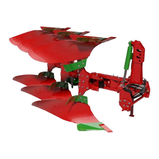
GENERAL INFORMATION 6.2. Construction of plough plough rotation skim coulter body head cylinder beam support foot frame ground following wheel Overview of plough POM in version with skim coulters. plough firmer support mouldboard beam firmer holder mounting support holder frog blade breast landside... -
Page 29: Maintenance And Service
OPERATION VII. MAINTENANCE AND SERVICE Before working, it is necessary to carefully get acquainted with the function and construction of the tractor's and plough's parts. 7.1. Preparation of the tractor to work with the plough REMEMBER! In order to make proper adjustments of the below-described sub-assemblies of the tractor, observe the provisions specified in the instruction manual provided by the tractor manufacturer. -
Page 30: Three-Point Linkage
OPERATION 7.1.3. Three-point linkage The construction of the three-point linkage is based on the principle that the tractor and the mounted machine are intended to operate as an integral assembly. The functionality of such assembly depends on a setting of the upper link (1) and lower links (2) adjusted on hangers (3). -
Page 31: Front Axle Load
OPERATION 7.1.5. Front axle load The tractor must be equipped with front weights (1) to ensure the optimum driving properties, proper mass distribution and equal working depth of ploughing. The calculation procedure of the counterweight mass for the plough as the ballast weights mounted in front of the tractor is discussed in the “Stability of the tractor-plough assembly”... -
Page 32: Mounting The Plough On The Tractor
OPERATION 7.2.1. Mounting the plough on the tractor In order to attach the plough correctly and safely, the tractor should stand on a firm and level ground. While mounting the plough on the tractor proceed as follows: switch the tractor's hydraulic system into position adjustment, •... -
Page 33: Start Of Ploughing
OPERATION 7.3. Start of ploughing The arrangements indicated below are essential, particularly if the plough is operated for the very first time. 7.3.1. Upper attachment point The plough can be connected to the end of the tractor's upper link by means of permanent holes (OS) or floating... -
Page 34: Bodies
OPERATION When starting ploughing, in order to properly set the plough, note which direction the tractor tends to veer to. If it turns towards the ploughed soil, loosen the internal spindle, and if it turns towards unploughed field tighten the internal spindle. While external spindle (2) is used for changing of the furrow width. -
Page 35: Mouldboards
OPERATION However, if value of the angle of approach is too high, this can result in undesired resistance and problems maintaining the same ploughing depth, and finally, significant increase in fuel consumption. When adjusting the body, do not loosen fastening bolts completely to prevent detachment of elements of the body! 7.3.4. - Page 36 OPERATION Wheel support has a few-step vertical adjustment, separately for the plough's right and left side (screws S1 and S2). In connection with the tractor's hydraulic system, used for lifting and lowering of the plough, the adjustable support wheel can be used for ploughing depth adjustment.
-
Page 37: Adjustment Of Vertical Tilt
OPERATION 7.3.6. Adjustment of vertical tilt After setting of a desired ploughing depth and setting of the tractor so that right or left wheels are level on a furrow, adjust proper working angle for the whole machine (vertical adjustment). It is desirable that in ploughing position, between the ground and... -
Page 38: Plough Rotation
OPERATION 7.4. Plough rotation The plough's rotary mechanism is based on two- side action rotation cylinder (1). The cylinder is mounted at the back of hanger's turret which enables smooth and safe rotation. External spindle (2) should be adjusted so that when the plough is lifted, the machine has a sufficient clearance from the ground to ensure a collision-free full rotation, taking into account also a change in the support wheel's position during this procedure. -
Page 39: Safety Devices
OPERATION 7.5. Safety devices The simplest in use and the most effective stone protection device. Each plough body is protected with shear bolts (s) of adequate hardness. These bolts are mounted in upper holes on the plough beam and holder mounting the whole body on the frame. - Page 40 OPERATION During ploughing keep away from the area of plough body release! Keep a safe distance! WARNING! Exercise particular caution when replacing shear bolt. Within the area of protection of the plough body with shear bolt, there are cutting and crushing risk points! ATTENTION! Do not rotate the plough with released body! This may cause damage to the machine!
-
Page 41: Transport
8.1. Delivery and unloading If the machine is purchased directly from the manufacturer, the transport conditions are determined by AGRO-MASZ, if no other arrangements are made with the customer. The delivery time-limit is settled by the manufacturer in consultation with the customer. The seller (manufacturer) is responsible for the proper packaging and protection of the machine for the time of transport. -
Page 42: Transport - Driving On Public Roads
TRANSPORT 8.2. Transport – driving on public roads Take care as the machine can swing beyond the outline of the tractor at the corners! Before transport, fix supports of the tractor's lower links to limit the sideways movements of the machine! For transport on public roads the machine is driven being lifted on the tractor's three-point linkage. -
Page 43: Maintenance
MAINTENANCE MAINTENANCE The machine can be repaired and serviced only by personnel with proper knowledge and being familiar with the possible risk and instruction manual! To keep the plough in the best technical condition and its optimum service lifetime, maintain its elements in accordance with the below-mentioned schedule. - Page 44 MAINTENANCE Rotation bearing Mounting of ground following wheel bracket Pins of frame-hanger joint Pins of frame-hanger joint...
-
Page 45: Bolt Tightening
Bottle screws Tilt cylinder joints REMEMBER! For maintenance, use adequate enriched grease! Use of a grease of inadequate parameters can result in the faster wear of the plough parts or their breakdown! 9.2. Bolt tightening The machine is provided with bolts with hardness grade of 8.8, 10.9 and 12.9. -
Page 46: Instructions For Proper Operation
MAINTENANCE REMEMBER! Damaged bolts should be replaced with new ones of the same quality. Control the tightening torque of bolts during operation! Tighten all bolts and nuts after the first day of operation! Tighten all bolts and nuts after the end of the working season! ATTENTION! It is forbidden to use bolts with the parameters other than applied by the manufacturer! SIZE... - Page 47 Correct vertical setting of the plough.
- Page 48 OPERATION Incorrect vertical settings of the plough. As far as the quality of work is concerned, it is important to have the depth correctly set. Maximum working depth should not be greater than 2/3 of the furrow width, which in normal soil conditions will allow to produce furrows which are properly turned over and balanced.
- Page 49 Correct horizontal setting of the plough. Incorrect horizontal setting of the machine.
- Page 50 OPERATION Ploughing quality is significantly influenced by an apparently obvious matter of turning on headlands. It is recommended to take turns using either of two methods: • Turn by 360 – when approaching the edge of the field, start the plough lifting function at the same time turning maximally to the ploughed part of the field, and shortly after that smoothly turn the steering wheel maximally to the opposite direction, and then...
-
Page 51: Detachment Of Plough
MAINTENANCE 9.4. Detachment of plough The plough always should be parked on a firm and level ground. To safely detach the plough from the tractor: • turn the plough to working position and lower it so it is supported with right bodies on the ground, turn the tractor's engine off and remove the ignition key, •... -
Page 52: Storage
MAINTENANCE 9.5. Storage The machine should be cleaned on regular basis, taking particular care after the end of the working season for a storing period between the working seasons, which will affect its service lifetime. The plough can be cleaned by means of compressed air or a pressure washer. -
Page 53: Defects And Their Elimination
MAINTENANCE Ploughshares should be replaced in good time before section where the chisel is bolted is affected by wear. However a ploughshare can be recovered, if its wear allows for this. Mouldboards should be replaced together with supports, if there is a deterioration in dumping of a produced furrow, or eventually, if the element starts to get deformed. - Page 54 MAINTENANCE MALFUNCTION POSSIBLE CAUSE REPAIR ACTION Tractor front section is Improper additional Mount more front axis lifted loading of tractor front weights on tractor section in relation to plough's weight Fill front tyres with liquid (if provided by the tractor manufacturer) Plough does not Upper link on tractor's...
-
Page 55: Environmental Protection
MAINTENANCE 9.8. Environmental protection When the machine is significantly worn, as a result of the expiry of its service lifetime, it should be utilised by a specialist company, in accordance with the applicable environmental protection regulations. Worn and damaged parts of the machine, replaced with the new ones, should be dealt in a special way, as well. - Page 56 NOTEBOOK NOTES...
- Page 57 INDEX INDEX...
-
Page 58: Warranty Certificate
+48 661 076 457. For proper warranty service, in addition to the afore-mentioned notification, the machine's user should submit photographs of the machine showing the defect at: serwis@agro-masz.eu. 10.1. Warranty terms The “user”, as referred herein, means any natural or legal person purchasing agricultural equipment;... -
Page 59: Warranty Table
WARRANTY 10.2. Warranty table MACHINE INFORMATION Plough symbol Factory number Date of sale Manufacturer's signature and stamp Seller's signature and stamp ATTENTION! When the product is purchased, request the seller to fill in exactly the warranty certificate, specifying the date and place of sale and have the data confirmed with the seller’s stamp and signature. - Page 60 WARRANTY SCOPE OF REPAIRS DATE, REPAIR CONTRACTOR'S SIGNATURE STAMP...
- Page 61 PARTS CATALOGUE PARTS CATALOGUE Spare parts can be purchased at the point where the machine was sold, or at the machine's manufacturer. When ordering spare parts include the following data: • machine symbol, year of manufacture, factory number (see data plate), •...
- Page 62 PARTS CATALOGUE Fig. R1 PLM0015 Plough POM 3+1 (pictograms) LIST OF PARTS QUANTITY REFERENCE NUMBER DESCRIPTION EW00060 Warning pictogram - Read the Manual Warning pictogram - Stop the engine before any EW00061 servicing Warning pictogram - Risk of crushing of the EW00063 limbs by working elements of the machine or cutting by sharp edges...
- Page 63 Rotary plough POM body with mounting PL01488 Rotary plough POM body with mounting EW00194 Rubber plug 100x100 Ground-following wheel mechanism side frame PL01525 100x100 PL01540 Bottle screw - ruling POM2 PL00789 Link 470mm PL01544 Foot PL01739 Hinge POM complete PL01774-02 Frame POM3...
- Page 64 Fig. R3 PL01321 Hitch with turntable POM...
- Page 65 LIST OF PARTS QUANTITY REFERENCE NUMBER DESCRIPTION EL00060 Tapered roller bearing 32018 EL00061 Tapered roller bearing 32216 PL01324 Hitch POM PL01325 Dust protection EL00058 Bearing nut KM16 EL00059 Bearing washer MB16 PL01327 Turntable POM PL01351 Sliding sleeve 45x50 Grease nipple Type A DIN 71412 - AM8 x 1 conical EL00020 short PL01345...
- Page 66 Fig. R4 PL01739 Hinge POM complete LIST OF PARTS QUANTITY REFERENCE NUMBER DESCRIPTION PL01734 POM hinge reinforcement P16/O Flat washer M16 zinc plated S16x70/8.8/O Bolt M16x70 8.8 zinc-plated NS16/O Locknut M16 8 zinc plated PL01745 Pin dia45 PL01743 Hinge flat POM PL01732 Hinge flat POM EL00043...
- Page 67 Fig. R5 PL01485 Coupling LIST OF PARTS QUANTITY REFERENCE NUMBER DESCRIPTION PL01483 Pin dia25xL157 EL00044 Spring peg dia10xL45 PL01486 Connector PL01351 Sliding sleeve 45x50 P16/O Flat washer M16 zinc plated S16x150/8.8/O Bolt M16x150 8.8 zinc-plated PL01495 Sleeve 16x28x89 Grease nipple Type A DIN 71412 - AM8 x 1 conical EL00020 short S16x170/8.8/O...
- Page 68 Fig. R6 PL01487 Rotary plough POM body with mounting LIST OF PARTS QUANTITY REFERENCE NUMBER DESCRIPTION PL01476 Second pair of bodies PL01477 Pocket holder lower PL01478 Pocket holder upper P20/O Flat washer M20 zinc plated S20x150/8.8/O Bolt M20x150 8.8 zinc-plated NS20/O Locknut M20 zinc plated P16/O...
- Page 69 Fig. R7 PL01476 Rotary plough POM body LIST OF PARTS QUANTITY REFERENCE NUMBER DESCRIPTION PL01443 Right frog complete POM PL01449 Left frog complete POM PL01457 Pocket vertical plate P12/O Flat washer M12 zinc plated S12x70/8.8/O Bolt M12x70 8.8 zinc-plated N12/5.8/O Flat washer M12 5.8 zinc plated P20/O Flat washer M20 zinc plated...
- Page 70 Fig. R8 PL01443 Right frog complete POM...
- Page 71 LIST OF PARTS QUANTITY REFERENCE NUMBER DESCRIPTION PL01436 Frog right PJL PL01391 Mouldboard right 14" PL01431 Breast right 14" PL01429 Ploughshare right 14'' PL01444 Plough beam POM PO.ET.00021 Angle adjustment screw P16/O Flat washer M16 zinc plated N16/10/0 Flat washer M16 10 zinc plated N20/8.0/C Flat washer M20 8.0 black PO.WG.00029...
- Page 72 Fig. R9 PL01449 Left frog complete POM...
- Page 73 LIST OF PARTS QUANTITY REFERENCE NUMBER DESCRIPTION PL01448 Left frog PL01444 Plough beam POM PO.ET.00021 Angle adjustment screw P16/O Flat washer M16 zinc plated N16/10/0 Flat washer M16 10 zinc plated N20/8.0/C Flat washer M20 8.0 black PL00871 Landslide POL 2015 SP12x35/8.8/O Plough bolt M12x35 8.8 zinc plated N12/5.8/O...
- Page 74 Fig. R13 PL01525 Ground-following wheel mechanism side frame 100x100...
- Page 75 LIST OF PARTS QUANTITY REFERENCE NUMBER DESCRIPTION PL01523 Wheel mounting PL01297 Mechanism for flat S20x60/8.8/O Bolt M20x60 8.8 zinc-plated Grease nipple Type A DIN 71412 - AM8 x 1 conical EL00020 short PZ.EM.00003 Rim with tyre PZ40 PJ PL01528 Wheel hub POM complete P16/O Flat washer M16 zinc plated S16x45/8.8/O...
- Page 76 Fig. R14 PL01528 Wheel hub POM LIST OF PARTS QUANTITY REFERENCE NUMBER DESCRIPTION EL00018 Bearing washer MB6 EL00019 Bearing nut KM6 PL00454 Hub dust nut PL01527 Wheel axle POM NS30/O Locknut M30 zinc plated P30/O Flat washer M30 zinc plated SI00916 Housing of maintenance-free hub (SR, PJ, PZ, POM) EL00016...
Need help?
Do you have a question about the POM3 and is the answer not in the manual?
Questions and answers