Sign In
Upload
Download
Table of Contents
Contents
Add to my manuals
Delete from my manuals
Share
URL of this page:
HTML Link:
Bookmark this page
Add
Manual will be automatically added to "My Manuals"
Print this page
×
Bookmark added
×
Added to my manuals
Manuals
Brands
PreCise Manuals
Robotics
PF3400
Hardware reference manual
PreCise PF3400 Hardware Reference Manual
Hide thumbs
1
2
3
4
5
6
7
8
9
10
11
12
13
14
15
16
17
18
19
20
21
22
23
24
25
26
27
28
29
30
31
32
33
34
35
36
37
38
39
40
41
42
43
44
45
46
47
48
49
50
51
52
53
54
55
56
57
58
59
60
61
62
63
64
65
66
67
68
69
70
71
72
73
74
75
76
77
78
79
80
81
82
83
84
85
86
87
88
89
90
91
92
93
94
95
96
97
98
99
100
101
102
103
104
105
106
107
108
109
110
111
112
113
114
115
116
117
118
119
120
121
122
123
124
125
126
127
128
129
130
131
132
133
134
135
136
137
138
139
140
141
142
143
144
145
146
147
148
149
150
151
152
153
154
155
156
157
158
159
160
161
162
163
164
165
166
167
168
169
170
171
Table Of Contents
172
page
of
172
Go
/
172
Contents
Table of Contents
Troubleshooting
Bookmarks
Table of Contents
Warning Labels
Table of Contents
Introduction to the Hardware
System Overview
System Description
PF3400: 3Kg Version
System Diagram and Coordinate Systems
System Components
Preciseflex 400 Robot
Optional Linear Axis Module
Mounting of Robot and Linear Axis Module
Optional Gripper
Guidance 1400B Controller
Low Voltage Power Supplies
Energy Dump Circuit
Remote Front Panel, E-Stop Box and Manual Control Pendant
Optional RS485 IO Module (GIO)
Remote IO Module (Ethernet Version)
Machine Vision Software and Cameras
Machine Safety
Safety and Agency Certifications
Standards Compliance and Agency Certifications
Moving Machine Safety
Voltage and Power Considerations
Mechanical and Software Limit Stops
Stopping Time and Distance
Releasing a Trapped Operator: Brake Release Switch
Collaborative Robot Safety
Summary
Background
Power and Force Limiting by Inherent Design or Control
Maximum Allowable Forces to Prevent Operator Injury
Limit Values
Types of Forces
Robot Testing and Safety Circuits
Controller Requirements
Possible Precise Controller Faults and Controller Testing
Safety Circuits, Failure Modes, and TUV Testing for the PF400 Robots
PF400 Maximum Forces, Newton
Test Procedure for the PF400
Vertical and Horizontal Test Setup
Free Space Collision Test and Linear Rail Test
Robot Workcell Design
Workcell Design Recommendations for the PF400
Normal Operator Interaction with Robot
Possible Low Frequency (Rare) Interaction with Robot
Appendix A: Example Performance Level Evaluation for PF400
Appendix B: TUV Verification of PF400 Collision Forces
Description of the Test Subject
Function
Technical Data
Order
Positive Test/Evaluation Results
Collision Force Table for PF3400
PAC Files Preciseflex 3400S
Table A2 from ISO/TS 15066: 2016
Biomechnical Limits
Safety Circuits for PF400 500Gm Payload
Safety Circuits for PF3400 3Kg Payload
PF400 500Gm Safety Circuits
PF3400 3Kg Safety Circuits
Installation Information
Environmental Specifications
Facilities Connections
System Dimensions
Working Volume
Mounting Dimensions for PF400, Standard Reach
Finger Mount Height from Base PF400
Gripper Flange Mount Height from PF3400
Linear Axis Mounting Dimensions
Mounting Instructions
Tool Mounting – Preciseflex 400
Accessing the Robot Controller
Power Requirements
Emergency Stop
Hardware Reference
System Schematics
System Diagram and Power Supplies
Schematic: System Overview
Schematic: FFC Boards Revision B PF400
Schematic: FFC Boards Revision C PF400
Schematic: FFC Boards 3Kg PF400
Schematic: Safety System Overview PF400 CAT3
Controller Power Amplifier Connectors
Control Board Connectors
Gripper and Linear Axis Controller Connectors
Facilities Panel
E-Stop Connector
MCP / E-Stop Interface
Digital Input Signals
Sinking Digital Input
Sourcing Digital Input
Digital Output Signals
Sinking Digital Output
Sourcing Digital Output
Gripper Controller Digital Inputs and Outputs
RS485 Remote IO Module (GIO)
PF3400 3Kg IO in Base of Robot (GIO)
Digital Outputs in the Outer Link
Ethernet Interface
RS-232 Serial Interface
Software Reference
Accessing the Web Server
Loading a Project (Program) or Updating PAC Files
Updating GPL (System Software) or FPGA (Firmware)
Recovering from Corrupted PAC Files
Adding or Removing the Optional Linear Axis
Controlling the Precise Servo Grippers
Software Revision
Controlling the Gripper
Gripper Squeeze (Simple Method)
Gripper Squeeze (Asymmetric Method)
End of Travel Sensor
Grip Test and Squeeze Check
Servo Gripper Controller Digital Inputs and Outputs
Optional Pneumatic or Vacuum Gripper
J4 and J7 on GSB Board
J14 and J15 on CPU Board
G1400B Dedicated Digital Outputs
Service Procedures
Recommended Tools
Trouble Shooting
Recommended Action
Encoder Operation Error
Replacing the Encoder Battery
Tools Required
Parts Required
Calibrating the Robot: Setting the Encoder Zero Positions
To Replace the Encoder Battery the User Must
Replacing Belts and Motors
General Belt Tensioning
Tensioning the J1 (Z Column) Belts
Tensioning the J2 Belt
Tensioning the J3 Belt (before 2014)
Tensioning the J4 Belt (before 2014)
Tensioning the J3 and J4 Belts (2014)
Motor Locking Screws
Tensioning the Belt on the Optional Linear Axis
To Tension the Linear Axis Belt the User Must
Replacing the Power Supplies
Spare Parts Required
Replacing the Robot Controller
Replacing the Servo Gripper Controller
Controller Installed in Inner Link
Wiring for 60N Gripper with Battery Pigtail
Wiring for Pneumatic Gripper
Wiring for Vacuum Gripper
Wiring for Vacuum-Pallet Gripper
Replacing the Agilent Servo Gripper Finger Pads
Replacing the Gripper Spring or Cable
Spare Parts Required: Spring or Cable Assembly
Adjusting the Gripper Backlash or Centering Fingers
Gripper Racks Centered in Fully Closed Position
Gripper Racks Centered in Fully Open Position
Adjusting the Gripper Brake (for Grippers with Brake)
Replacing the Electric Grippers or Slip Ring Harness
Replacing the Linear Axis Controller
Installing the Optional GIO Board
To Install the GIO in a Robot
Replacing the Main Harness
Replacing the Outer Link Harness
Replacing the Z Axis Motor Assembly
Replacing the J3 (Elbow) Axis Motor or Timing Belt
Replacing the J4 (Wrist) Axis Motor or Timing Belt
Replacing Servo Gripper with Pneumatic or Vacuum Gripper
Product Specifications
Preciseflex 400 Specifications
General Specification
Preciseflex 3400 Specifications
Appendix C: Spare Parts List
Appendix D: Preventative Maintenance
Check List
To Use the Tension Meter
Appendix E: Belt Tensions, Gates Tension Meter
Advertisement
Quick Links
1
Hardware Reference
Download this manual
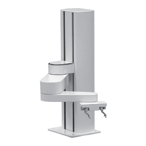
The PF400 and PF3400 Robots
Hardware Reference
Manual
Version 5.04, August 9, 2017
Precise Automation Inc., 727 Filip Road, Los Altos, California 94024
www.preciseautomation.com
Table of
Contents
Previous
Page
Next
Page
1
2
3
4
5
Advertisement
Table of Contents
Need help?
Do you have a question about the PF3400 and is the answer not in the manual?
Ask a question
Questions and answers
Related Manuals for PreCise PF3400
Robotics PreCise PF400 Hardware Reference Manual
(172 pages)
Table of Contents
Save PDF
Print
Rename the bookmark
Delete bookmark?
Delete from my manuals?
Login
Sign In
OR
Sign in with Facebook
Sign in with Google
Upload manual
Upload from disk
Upload from URL
Need help?
Do you have a question about the PF3400 and is the answer not in the manual?
Questions and answers