Table of Contents
Advertisement
Quick Links
Advertisement
Table of Contents

Related Manuals for Emtron ELC2


Summary of Contents for Emtron ELC2
- Page 1 Emtron Lambda to USER MANUAL Rev 1.1...
- Page 2 EMTRON ELC USER MANUAL WWW.EMTRON.WORLD Kit Contents When purchasing an ELC1/ELC2 the following items are included: ▪ ELC1/2 Device with Flying Harness ▪ Deustch DTM 4-way mating connector with female pins (DTM06-4S) ELC2 kit pictured. When purchasing an ELC2M the loom side mating Autosport connector is not included but can be purchased separately.
-
Page 3: Table Of Contents
7.23 ECU CAN Configuration for Multiple Devices ............19 8.0 ECU Channel Configuration ....................20 9.0 ELC Custom Device Settings ....................22 10.0 Ordering Information ....................... 23 Appendices ..........................24 Appendix 1 – CAN Bus Data Packaging ................24 © EMTRON AUSTRALIA PTY LTD MARCH 2018... -
Page 4: Description
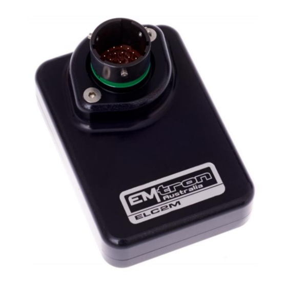
EMTRON ELC USER MANUAL WWW.EMTRON.WORLD 1.0 Description The Emtron Lambda to CAN devices are available in both Standard and Mil Spec versions. ELC2M The ELC2M is a Mil Spec Dual Channel Lambda to CAN device using the Motorsport proven Deutsch Autosport connector system(Green). - Page 5 DTM connector. The waterproof enclosure is extremely compact and made from billet 6061 aluminium. All devices control the Bosch LSU4.9 Lambda Sensor and are compatible with all Emtron ECUs. Bosch proven integrated circuit technology is used for sensor control, Nernst Cell temperature measurement with advanced PID algorithms for precise heater control.
-
Page 6: Specification
▪ Enclosure Size 52 mm x 74 mm x 18 mm ▪ 125g (Excludes loom) ELC1/ ELC2 ▪ Enclosure Size 63mm x 54 mm x 20mm ▪ ELC1 165g, ELC2 200g (includes flying loom) © EMTRON AUSTRALIA PTY LTD MARCH 2018... -
Page 7: Installation
Lambda Flying Loom Connector: Bosch LSU 4.9 (F) Function Wire Colour Pump Current Virtual Ground Yellow Heater Ground White Heater 12 Supply Grey Cal Resistor Orange Nernst Cell Voltage Black Table 3.1 ELC1/2 LSU 4.9 Connector Pinout © EMTRON AUSTRALIA PTY LTD MARCH 2018... -
Page 8: Elc2M Wiring
Lambda 1 Heater Ground Lambda 2 Heater Ground Lambda 1 Heater 14V Supply (Protected) Lambda 2 Heater 14V Supply (Protected) (Not used) (Not used) (Not used) (Not used) (Not used) (Not used) Table 3.2. ELC2M Pinout © EMTRON AUSTRALIA PTY LTD MARCH 2018... -
Page 9: Bosch Lsu4.9 Sensor Wiring
Table 3.3. Bosch LSU 4.9 Sensor Pinout Figure 3.0. LSU4.9 Connector Pinout NOTE: To avoid signal errors and loss of accuracy, a cable of a maximum length of 1.5 m between sensor and ELC is recommended. © EMTRON AUSTRALIA PTY LTD MARCH 2018... -
Page 10: Can Bus Wiring
3.2 show possible CAN Bus Implementation examples Figure 3.1. CAN Bus Wiring Example. ECU and Dash at each end with 120 Ohm Termination Figure 3.2. CAN Bus Wiring Example. ECU and ELC2 at each end with 120 Ohm Termination © EMTRON AUSTRALIA PTY LTD MARCH 2018... -
Page 11: Elc Can Bus
All devices on the CAN Bus must be configured to use the same baud rate. For this reason, all Emtron CAN devices will Auto-scan the CAN bus until a successful baud rate has been detected. Once detected this rate will be stored and used at the next power up. -
Page 12: Noise Immunity
40mm of cable. This is very important and should always be implemented on both CAN Bus and LSU Sensor wiring. Pair 1 Pair 2 CAN High <-------> CAN Low Pump Current <-------> Cal Resistor Nernst Cell <-------> Virtual Ground Voltage Table 3.4. Wire pairing for twisting © EMTRON AUSTRALIA PTY LTD MARCH 2018... -
Page 13: Lambda Sensor Installation
Winter and salted roads compound this issue. Always check for a cracked or broken connector when strange results occur. © EMTRON AUSTRALIA PTY LTD MARCH 2018... -
Page 14: Heater Control And Sensor Calibration
For maximum sensor life the ECU should control heater start-up. It does this by communicating with the ELC over CAN Bus. For setup options see Config View -> Communications Tab -> Emtron CAN Device -> Emtron Lambda to CAN (ELC/ELCM) Setup. See Figure 5.0. -
Page 15: Exhaust Back Pressure (Emap) Compensation
The EMAP setting can be enabled by going to the the Config View -> Communications Tab -> Emtron CAN Device -> Emtron Lambda to CAN (ELC/ELCM) Setup and selecting the “Enable EMAP” setting to ON (Figure 6.0). Once enabled to ECU will transmit the EMAP value over the CAN Bus and the ELC will received this value so the correction can be applied. -
Page 16: Elc Device Configuration
To confirm the ELC device has been detected, connect to the ECU using Emtune. Open the ECU Runtime menu (F3) and select the Communications Tab. Within this tab there will be a list of Emtron CAN devices the ECU has detected. It will list: 1. CAN Device Model 2. -
Page 17: Ecu Can Channel Configuration For Single Device
2. Set "CAN Base Address" to the ID shown in Figure 7.0/7.1 In this example its ID 671. 3. Set "DATA Set" to 50 (ELC/ELC2M 1x Device). See Figure 7.2. The ECU in now configured and reading the data from the ELC Device. Figure 7.2. ELC CAN Configuration © EMTRON AUSTRALIA PTY LTD MARCH 2018... -
Page 18: Elc Multiple Device Setup
To confirm the ELC device has been detected, connect to the ECU using Emtune. Open the ECU Runtime menu (F3) and select the Communications Tab. Within this tab there will be a list of Emtron CAN devices the ECU has detected. It will list: 1. CAN Device Model 2. -
Page 19: Elc Can Base Address Id Reprogramming
To ensure each ELC device has a unique ID from the example in Figure 7.3, ELC2 Device 2 (SN 1242) needs a new Base Address of 673. This is easily done using Emtune from the Config view -> Communications Menu -> Emtron CAN Devices -> Emtron CAN Device Programming menu In this example, ELC Device 2 will need to have its Base Address re-programmed to 673. -
Page 20: Ecu Can Configuration For Multiple Devices
Lowest Base Address ID shown in Figure 7.5. In this example its 671. 3. Set "DATA Set" to 51 -Emtron ELC/ELCM 2x Devices (CAN PID 671/673). The ECU is now configured and will receive data from all devices on IDs 671-672, 673-674. -
Page 21: Ecu Channel Configuration
Option A: Use the Lambda 1 and Lambda 2 Input Channel(s) as shown in Figure 8.0. With a ELC1 set the Lambda 1 to CAN ELC #1 Ch-A and for an ELC2 set Lambda 1 to CAN ELC #1 Ch- A and Lambda 2 to CAN ELC #1 Ch-B. - Page 22 Channel B to Cylinder 4; set the Channel Input Source for Lambda Cyl 4 to CAN ELC #2 Ch-B … etc for ELC Device 3 and 4 Figure 8.2. Multiple ELC devices channel assignments © EMTRON AUSTRALIA PTY LTD MARCH 2018...
-
Page 23: Elc Custom Device Settings
5. ELC Heater Post Start Lockout (See Section 5.0) 6. ELC Lambda 1 Test Enable 7. ELC Lambda 2 Test Enable These settings are available from the Config View -> Communications Tab -> Emtron CAN Device -> Emtron Lambda to CAN (ELC/ELCM) Setup". See Figure 9.0 Figure 9.0 The ELC Lambda 1 and 2 Test Enable setting will force the ELC device to send the Test Lambda value over the CAN bus. -
Page 24: Ordering Information
EMTRON ELC USER MANUAL WWW.EMTRON.WORLD 10.0 Ordering Information Product Part Number Emtron ELC1 5123-1 Emtron ELC2 5123-2 Emtron ELC2M 5123-213 © EMTRON AUSTRALIA PTY LTD MARCH 2018... -
Page 25: Appendices
This section outlines the CAN Protocol used to communicate with the ELC device(s). If the device is connected to an Emtron ECU, the CAN Bus packet is automatically decoded when CAN ELC Dataset is selected and no additional setup is required. For more information refer... - Page 26 Multiplier Offset Units Example CAN ID 672/0x290 Index = 0 Lambda 2 0.001 897 = 0.897 La Pump Current 2 0.001 132 = 0.132mA Fault 2 Status 2 Heater 2 DC 42 = 42%DC © EMTRON AUSTRALIA PTY LTD MARCH 2018...
- Page 27 22 = Pump Cal Data Invalid 19 = Lambda Stability Error 20 = Error Reading Chip ID 22 = System Voltage Low 22 = Cannot enter Calibration mode 23 = Cannot enter standalone mode © EMTRON AUSTRALIA PTY LTD MARCH 2018...
- Page 28 EMTRON ELC USER MANUAL WWW.EMTRON.WORLD Emtron Australia Pty Ltd Unit 8, 36 Lidco Street Arndell Park NSW 2148 Australia (See the www for contact information) www.emtron.world www.emtronaustralia.com.au © EMTRON AUSTRALIA PTY LTD MARCH 2018...
Need help?
Do you have a question about the ELC2 and is the answer not in the manual?
Questions and answers