Table of Contents
Advertisement
Quick Links
Advertisement
Table of Contents

Related Manuals for Emtron EIC10


Summary of Contents for Emtron EIC10
- Page 1 Emtron Input USER MANUAL Expansion to CAN Rev 1.0...
- Page 2 EMTRON EIC USER MANUAL WWW.EMTRON.WORLD Kit Contents When purchasing an EIC10 the following items are included: ▪ EIC10 Device with Flying Harness ▪ Deustch DTM 4-way connector and female pins (DTM06-4S) ▪ Deustch DTM 12-way connector and male pins (DTM04-12PA) EIC10 kit pictured.
-
Page 3: Table Of Contents
5.0 ECU Channel Configuration ....................20 6.0 EIC Custom Settings ......................21 7.0 Ordering Information ......................24 Appendices ..........................25 Appendix 1. CAN Bus Data Packaging .................. 25 Appendix B. Magneto-Resistive Sensors ................32 © EMTRON AUSTRALIA PTY LTD APRIL 2018... -
Page 4: Description
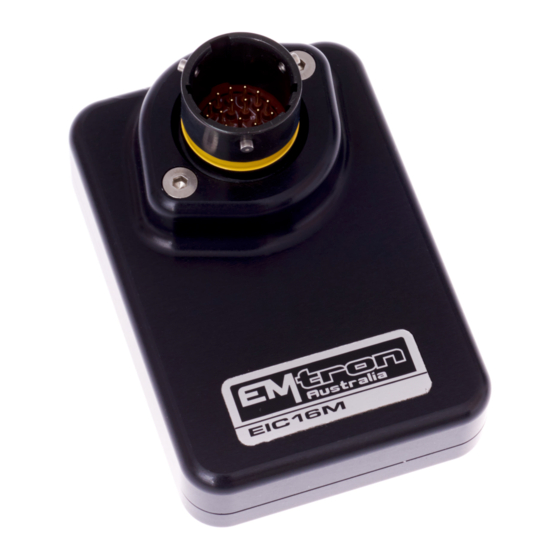
EIC16M The EIC16M is a Mil Spec device designed to increase the Input channel capability of all Emtron ECUs with 16 high resolution analog and/or 4 frequency based inputs. The device is connected via CAN bus and will be automatically detected which will significantly minimalize configuration time. -
Page 5: Specification
Analog Inputs 0.0 – 16.0V range. Resolution. 4.02mV 12 Bit o Switchable 1k Pullups with blocking diode to 8V Supply o Range 0.5Hz up to 6500.0Hz, Resolution. 0.1Hz Outputs ▪ 5V Sensor Supply. Output current 250mA. Short circuit to ground protected. © EMTRON AUSTRALIA PTY LTD APRIL 2018... - Page 6 ▪ Operating Temperature Range: -30 to 100°C (-22 to 212°F) Physical EIC16M ▪ Enclosure Size 52 mm x 74 mm x 18 mm ▪ 125g EIC10 ▪ Enclosure Size 63mm x 54 mm x 20mm ▪ 160g © EMTRON AUSTRALIA PTY LTD APRIL 2018...
-
Page 7: Installation
Function Wire Colour Ground BLACK CAN Lo GREEN CAN Hi YELLOW 12V Supply Table3.0. EIC10 Power and CAN Deustch Connector Pinout Analog Input Flying Loom Connector: DTM 12 pin (F). Pin Function Voltage Pullup Wire Range Colour Analog Voltage 1 0 - 5.0V No... -
Page 8: Eic16M Pinout
0.0 – 16.5V Analog Voltage 14/Frequency 2 0.0 – 16.5V Analog Voltage 15/Frequency 3 0.0 – 16.5V Analog Voltage 16/Frequency 4 0.0 – 16.5V 5.0V Sensor Supply 0V Analog Sensor Reference Table 3.2. EIC16M Pinout © EMTRON AUSTRALIA PTY LTD APRIL 2018... -
Page 9: Can Bus
▪ Factory CAN Base Address of 718. Transmits data sequentially on the next 3 IDs. Total CAN ID Range is therefore 718 – 721. ▪ Up to 2x EIC10 devices can be used on the CAN Bus giving a total of 20 available Input Channels. -
Page 10: Pullup Resistors
3.4 Pullup Resistors EIC10 The EIC10 has no switchable pullups to 5V, so an external 1k resistor will need to be fitted when connecting to a temperature sensor. The 5V Analog Sensor Supply pin can be used as the pullup supply. -
Page 11: Frequency Inputs
EMTRON EIC USER MANUAL WWW.EMTRON.WORLD 3.5 Frequency Inputs The EIC10 and EIC16M have 4x Frequency Inputs which get shared with Analog Input pins as shown with Tables 3.3 and 3.4. o Range 0.2Hz up to 6500.0Hz o Resolution. 0.1Hz o Rising Edge Threshold = 1.7V o Falling Edge Threshold = 0.9V... -
Page 12: Noise Immunity
• DO NOT connect frequency based sensor grounds to the EIC 0V Reference pin; for example, an Ethanol content sensor. Use the main device ground. Figure 3.1. Correct MAP Sensor 0V Wiring Figure 3.2. Incorrect MAP Sensor 0V Wiring © EMTRON AUSTRALIA PTY LTD APRIL 2018... -
Page 13: Can Bus Wiring
High-Speed ISO 11898 Standard specification. See Figure 3.3. The EIC16M and EIC10 devices do not include an on-board CAN termination resistor, allowing the device to be wired at any position on the Bus. CAN Bus termination must be done correctly by using a 120 ohm 0.25W resistor at each end of the bus system as... - Page 14 EMTRON EIC USER MANUAL WWW.EMTRON.WORLD Figure 3.2. CAN Bus Wiring Example. ECU and EIC10 at each end with 120 Ohm Termination Figure 3.3. CAN Bus Wiring Example. Stub Length less than 0.3m © EMTRON AUSTRALIA PTY LTD APRIL 2018...
-
Page 15: Eic Device Configuration
4. Device Hardware Version 5. CAN Base Address ID With a single EIC10 device connected, the data should look as shown in Figure 4.0. With a single EIC16M device connected, the data should look as shown in Figure 4.1. Important: ▪... -
Page 16: Ecu Can Configuration For Single Device
2. Set "CAN Base Address" to the Base Address shown in Figure 4.0 / 4.1. In this example select 718 for EIC10 or 705 for EIC16M. 3. EIC10. Set "DATA Set" to 73 (EIC10 1x Device). See Figure 4.2 EIC16M. Set "DATA Set" to 69 (EIC16M 1x Device). See Figure 4.3 Figure 4.2. -
Page 17: Eic Data Monitoring For Single Device
As mentioned in section 3.4, the Base CAN Address ID used to transmit Data over the Bus by default is the same for each device type. The EIC10 has a factory CAN Base Address of 718 and EIC16M has a CAN Base Address of 705. When multiple EIC10/EIC16M devices are installed on the same CAN Bus, each device MUST have a unique CAN Base Address to avoid Bus conflicts. -
Page 18: Eic Multiple Device Detection
4. Device Hardware Version 5. CAN Base Address With 2x EIC10 devices connected to the CAN bus, the CAN Summary List should look similar to that shown in Figure 4.6. In this example the following devices have been detected: ▪ Device 1 - SN 1230 ▪... -
Page 19: Eic Can Base Address Id Reprogramming
WWW.EMTRON.WORLD 4.22 EIC CAN Base Address ID Reprogramming To ensure each EIC device has a unique ID from the example in Figure 4.6, EIC10 Device 2 needs a new Base Address of 722. This is easily done using Emtune from the Config view -> Communications Menu -> Emtron CAN Devices ->... -
Page 20: Ecu Can Configuration For Multiple Devices
4.24 EIC Data Monitoring for Multiple Devices To confirm the EIC10 data from multiple devices is being decoded by the ECU, open the Runtime menu (F3) -> Emtron CAN Device Tab to view the live data. © EMTRON AUSTRALIA PTY LTD APRIL 2018... -
Page 21: Ecu Channel Configuration
Compressor Outlet Temperature assigned to EIC16M channel 10 NOTE: EIC16M pullup control is done through the Config View-> Communications -> Emtron CAN Devices -> Emtron Input to CAN Expansion menu. See Section 6.2 for more information. Figure 5.0 © EMTRON AUSTRALIA PTY LTD APRIL 2018... -
Page 22: Eic Custom Settings
For these setting see Config view-> Communications -> Emtron CAN Devices -> Emtron Input to CAN Expansion. Inside this menu will be an EIC10 and EIC16M menu. The Default value is 200Hz. It can be adjusted to suit the application and available CAN Bandwidth. - Page 23 EMTRON EIC USER MANUAL WWW.EMTRON.WORLD Pullup Resistor Control Section 3.5 previously summarises the Pullup options. To adjust these setting see Config view-> Communications -> Emtron CAN Devices -> Emtron Input to CAN Expansion Figure 6.2. EIC10 Pullup Settings Figure 6.3. EIC16M Pullup Settings...
- Page 24 Falling. To adjust these setting see Config view-> Communications -> Emtron CAN Devices -> Emtron Input to CAN Expansion menu. NOTE: The Frequency will not read until the Input Channel is selected to ON (i.e. Falling or Rising edge).
-
Page 25: Ordering Information
EMTRON EIC USER MANUAL WWW.EMTRON.WORLD 7.0 Ordering Information Product Part Number Emtron EIC10 593-10 Emtron EIC16M 593-1613 © EMTRON AUSTRALIA PTY LTD APRIL 2018... -
Page 26: Appendices
This section outlines the CAN Protocol used to communicate with the EIC device(s). If the device is connected to an Emtron ECU, the CAN Bus packet is automatically decoded when correct CAN Dataset is selected and no additional setup is required. For more information refer to Section 4.0. - Page 27 0.0 V 5.0V AN Voltage 8 0.001 0.0 V 5.0V 707 /0x2C3 (Default) Data Voltage 3dp ID Type Standard 11-bit identifier Direction Transmit from Device Length 8 bytes Tx Rate Adjustable (50/100/200/500 Hz) © EMTRON AUSTRALIA PTY LTD APRIL 2018...
- Page 28 708/0x2C4 AN Voltage 13 0.001 0.0 V 16.5V CAN 13046 = 13.046V AN Voltage 14 0.001 0.0 V 16.5V AN Voltage 15 0.001 0.0 V 16.5V AN Voltage 16 0.001 0.0 V 16.5V © EMTRON AUSTRALIA PTY LTD APRIL 2018...
- Page 29 Byte Order Data Type CAN ID (bits) 710/0x2C6 5V Analog Supply Little Endian Unsigned Continuation: Name Multiplier Offset Units Example CAN ID 710/0x2C6 5V Analog Supply 0.001 0.0 V 5.5V CAN 4989 = 4.989V © EMTRON AUSTRALIA PTY LTD APRIL 2018...
- Page 30 Length Byte Order Data Type CAN ID (bits) 719/0x2CF AN Voltage 5 Little Endian Unsigned AN Voltage 6 Little Endian Unsigned AN Voltage 7 Little Endian Unsigned AN Voltage 8 Little Endian Unsigned © EMTRON AUSTRALIA PTY LTD APRIL 2018...
- Page 31 Example CAN ID 720/0x2D0 AN Voltage 9 0.001 0.0 V 5.0V CAN 3046 = 3.046V AN Voltage 10 0.001 0.0 V 5.0V 5V Analog Supply 0.001 0.0 V 5.5V CAN 4989 = 4.989V © EMTRON AUSTRALIA PTY LTD APRIL 2018...
- Page 32 Little Endian Unsigned Frequency 4 Little Endian Unsigned Continuation: Name Multiplier Offset Units Example CAN ID 721/0x2D1 Frequency 1 20000 CAN 65201 = 6520.1 Frequency 2 20000 Frequency 3 20000 Frequency 4 20000 © EMTRON AUSTRALIA PTY LTD APRIL 2018...
-
Page 33: Appendix B. Magneto-Resistive Sensors
Table 6.0 Device Connection An MT sensor can be connected directly to an Emtron ECU and the internal Scope function can be used to view the signal. Once you have the signal image, config the pullup resistor and correctly set the arming threshold. - Page 34 Figure 6.1 shows a scope trace of a MR Sensor with 330R pullup supplied at 8V. The High Output level is 5.9V and the Low Output Level is 3.6V. Figure 6.1. Scope trace of MR Sensor. © EMTRON AUSTRALIA PTY LTD APRIL 2018...
- Page 35 EMTRON EIC USER MANUAL WWW.EMTRON.WORLD Emtron Australia Pty Ltd Unit 8, 36 Lidco Street Arndell Park NSW 2148 Australia (See the www for contact information) www.emtron.world www.emtronaustralia.com.au © EMTRON AUSTRALIA PTY LTD APRIL 2018...
Need help?
Do you have a question about the EIC10 and is the answer not in the manual?
Questions and answers