Advertisement
Quick Links
Advertisement

Related Manuals for AML Colourbook 52F50


Summary of Contents for AML Colourbook 52F50
- Page 1 52F50 Lunchbox Compressor - Assembly manual [“Colourbook” Issue 1b]...
- Page 2 52F50 “Colourbook” Contents. Section 1 - “Colourbook” assembly guide Section 2 - Schematics diagrams and PCB Overlays Section 3 - Parts List Section 4 - Setup and Calibration...
- Page 3 52F50 “Colourbook” revision history Revision 1 ; Initial revision Revision 1a ; Added Schematics, overlays, calibration etc Revision 1b ; Added knob fitting page.
- Page 4 Output and 1mA Meter Termination Place a “blob” of solder across the two pads for 600 Ohm termination (SW10) and the 1mA meter selection pads (SW2)
- Page 5 Diodes D1, D2, D8, D24, D31, D32, D33 = 1N4001 or 1N4007...
- Page 6 Diodes D3-D7, D9, D18, D19 & D25-30 = BAX16 (14)
- Page 7 Diodes D20, D21, D22 & D23 = 1N4148 Matched Pairs D20 & D23 = Matched Pair D21 & D22 = Matched Pair...
- Page 8 Zener Diodes ZD2, ZD3, ZD4, ZD5, ZD6 = 2v7 ZD1 = 14v...
- Page 9 Resistors R66, R76, R79 = 0R R156 = 1R0 R116, R157 = 10R R105, R106, R115 = 15R...
- Page 10 Resistors R114 = 24R R113 = 33R R112 = 56R R104 = 68R...
- Page 11 Resistors R111 = 82R R150 = 91R R61, R110 = 120R R34 = 130R...
- Page 12 Resistors R33 = 150R R32 = 200R R18, R35, R49, R109 = 220R R31 = 240R...
- Page 13 Resistors R5, R50, R60, R84, R85 = 270R R30, R108 = 330R R29, R37, R90 = 390R R13, R27, R40, R128, R138 = 470R...
- Page 14 Resistors R28 = 510R R51, R64 = 560R R147 = 620R R24, R26, R107 = 680R...
- Page 15 Resistors R125 = 820R R103 = 910R R15, R23, R86, R87, R131 = 1k0 R22, R143 = 1k2...
- Page 16 Resistors R39, R47, R137, R146 = 1k5 R25, R53, R65, R81 = 1k8 R8, R14, R38, R48, R89, R130 = 2k2 R12, R57, R58, R73, R120 = 2k7...
- Page 17 Resistors R54, R102, R142 = 3k3 R88, R132 = 3k9 R63 = 4k7 R36, R119, R135 = 5k1...
- Page 18 Resistors R152 = 5k6 R45 = 6k8 R11 = 8k2 R1, R2, R17, R20, R75, R99, R101, R117, R145 = 10k...
- Page 19 Resistors R3, R4, R70 = 12k R19, R56, R59, R69, R74 = 15k R98, R148 = 18k R94 = 20k...
- Page 20 Resistors R9, R55, R71, R72, R153 = 22k R10 = 27k R46, R100, R124, R127, R149 = 33k R93, R97 = 39k...
- Page 21 Resistors R43, R96, R123, R126 = 47k R77, R141 = 56k R42, R95, R118, R121, R140 = 68k R6, R92 = 82k...
- Page 22 Resistors R21, R41, R82, R136, R151 = 100k R44, R122 = 120k R16 = 150k R91 = 180k...
- Page 23 Resistors R133, R134 = 220k R7, R80, R83, R144 = 1M0 F1, F2 = Ferrite Bead...
- Page 24 Ceramic C63 = 47pF Capacitors C11, C45 = 100pF C44, C62, C64 = 220pF...
-
Page 25: Ceramic Capacitors
Ceramic C24, C25, C26, C27, C53 = 330pF Capacitors C6, C7, C65 = 100nF... - Page 26 Resistors R154 = 10R / 3Watt R155 = 47R / 3Watt R68 = 470R / 3Watt...
- Page 27 Film C16, C46 = 680pF Capacitors C9, C19, C35, C48 = 1nF C14, C43 = 1n5F C40 = 4n7F...
- Page 28 Film C57 = 10nF Capacitors C60 = 100nF C61 = 330nF CL1 & CL2 = 100pF 3 Terminal L/C Network...
- Page 29 Meter Illumination LEDS D10 - D17 = LED 3mm Yellow Long leg “Flat” of LED Long leg...
- Page 30 Relays RL1-RL7 = 24 volt DIL DPDT **** NOTE ORIENTATION **** Tantalum Capacitor C36 = 22uF / 16v / Tantalum (1) **** NOTE ORIENTATION **** It is polarised, but difficult to see on the component. The positive terminal is marked by a very small “+”...
-
Page 31: Electrolytic Capacitors
Electrolytic C31 = 2.2uF / 63v Capacitors C22, C23, C32 = 10uF / 50v C1, C2, C3, C8, C12, C15, C17, C30, C34, C37, C38, C41, C50, C52, C55, C56 = 22uF / 63v (16) All positive terminals (the long lead) towards left. - Page 32 Electrolytic C5, C13, C28, C29, C39, C47, C51, C54, C58 = 100uF / 25v Capacitors C4, C21, C42 = 220uF / 25v C10, C33, C49 = 470uF / 16v All positive terminals (the long lead) towards left.
- Page 33 Small Signal Transistors Q5 Like this. Q5, Q22, Q23 = BC560C (All “flat side to the left” or Q22, Q23 Like this. “tag to the right”) Q20 = BCY70...
- Page 34 Small Signal Transistors Q1-Q4, Q6-Q19, Q21, Q24 = BC550C (20) (All “flat side to the left” except R52, R67, R129, R139 = 5k (or 4k7) (4) - Side adjust style on switch card) R62, R78 = 100k (2) - Side adjust style Q1-Q2 Like this.
-
Page 35: Headers And Jumpers
Headers J3 = 10 Way Box Header (1) ** Note orientation ** and Jumpers J5 = 20 Way Box Header (1) ** Note orientation ** PL9, PL10, PL11, PL12 = 2 Pin Jumper Fit Jumper Links PL9 = OFF PL10 = ON PL11 = ON PL12 = ON... - Page 36 Electrolytic Capacitors Molex KK Series - 8 way Tab towards output transformer and Molex C18, C20, C59 = 1000uF / 35v All positive terminals towards left M3 PCB Screw Fittings...
-
Page 37: Voltage Regulator
Voltage Regulator U1 fitting hint; U1 = 7808 voltage regulator Bend the pins of U1 before inserting in PCB. M3 Nyloc nut Insulating bush Insulating washer/sheet Bend the pins here... Approx 8-9mm from end. M3x8 SEMS screw... - Page 38 Output Transistor Q25 = TIP3055 Transistor HS1 = Heatsink TIP3055 + TO247 insulator (bush not required) Check Vertical Solder fully Insert heatsink through Tack in place first then check main PCB they are vertical before Tack in place. (Check orientation soldering completely.
-
Page 39: Rotary Switches
Rotary Switches SW4, SW8, SW9 = GR-03-002 (3) - 12 position, 1 pole, 1 gang SW6 = GR-03-003 (1) - 6 position, 2 pole, 1 gang After soldering the pins of SW6, trim the 2 common pins as short as possible Switch fitting hint;... - Page 40 Rotary Switch Adjustment Pins Fit pins in positions shown then apply the self adhesive silver washer over the pin holes to stop the pin coming out. [Discard the nut and shakeproof washer]. **** Make sure the spindle is in the position shown before fitting pins **** [0 clicks up from factory setting] (Threshold) pin at...
- Page 41 Input and interstage T2 = AML-18-003 (1) VERY IMPORTANT !!! NOTE ORIENTATION !!!! transformers Make certain that the pin numbers on the bottom of the transformer coincide with the numbers written on the PCB. T1 = AML-18-002 (1) If possible, lift the transformer about 2mm above the PCB when soldering so that there is a small gap between the transformer and PCB.
-
Page 42: Ribbon Cables
Ribbon Cables J1= 10 Way Ribbon Cable J2 = 20 Way Ribbon Cable... - Page 43 Toggle Switches Switch fitting hint; SW5 = 2 Way Toggle Switch SPDT (on-on) Horizontal type Important: The toggle switches are [Horizontal - sub-min CK-03-???] surprisingly sensitive to heat... solder (Mounted under PCB) one pin on each switch and then allow to cool before continuing. SW7, SW14 = 3 Way Toggle Switch SP3T (on-off-on) [Horizontal - sub-min CK-03-???] Make sure that the toggle switches are...
-
Page 44: Power Indicator Led
Power Indicator LED LED1 = Red LED - 3mm round (1) Fit the power indicator LED to the component side of the PCB such that the base of the LED aligns with the front edge of the PCB. Align rear edge of LED base..with edge of PCB Long Leg “Flat”... - Page 45 PL3 Fitting hint; Toggle Switch Push the long pins through the PCB and then (Vertical type) put a female jumper on the 2 middle pins to PL3 = 4 Way Right Angle Pin Header (1) hold it to the PCB... solder the outer pins and then remove the jumper to solder the middle pins SW1 = Toggle Switch DP3T (on-off-on)
- Page 46 Meter Switch PCB to Meter Drive PCB Attach the small toggle switch PCB to the UNDERSIDE of the meter drive PCB Such that the right angle pin header connects PL3 to PL4 Fit the pin header of PL3 into PL4...
- Page 47 Large Switch PCB to Main PCB Attach the large toggle switch PCB to the UNDERSIDE of the main PCB Such that the 8-way pin headers connects PL1 to PL5 and PL2 to PL6 The PCBs are separated by a 7mm gap. Fix using M3 x 16mm screws, 7mm spacers and Nyloc nuts Solder PL5 and PL6 after screwing together M3 x 16mm screw...
- Page 48 Output Transformer Assembly and Fitting VERY IMPORTANT: T3 = VTB2569 (1) Assembly Tip: Do NOT tighten the screws very tight... It is usually easier to plug in use a thread locking adhesive applied to the molex connector before screwing the transformer in the end of the screw.
- Page 49 Meter to Meter PCB assembly Remove the 2 small screws/washers and “top hat” fittings which hold the meter together and discard. Install the meter onto the PCB using M3 x 28mm screws, M3 plain washer and M3 x 4 mm threaded spacer. The M3 x 4mm threaded spacer should sit down into the hexagonal hole in the meter plastic body Put the spacer down into the hole and then screw the M3 x 28mm screw into it.
- Page 50 Meter Drive PCB to Meter Remove the meter electrical connection screws. Fit meter drive PCB over meter Plug the ribbon cable into J3 Refit meter electrical connection screws (discard the ring crimp terminals [solder tags]) Fit M3 Nyloc nuts to hold meter drive PCB DO NOT OVERTIGHTEN M3 Nylon Nuts.
-
Page 51: Chassis Assembly
Chassis Assembly 1] Remove the protective plastic coating from the chassis (if fitted). 2] Secure faceplate to chassis with 2 x M3 Nyloc Nuts 2 x M3 Nyloc nut Secure PCB to chassis with 4 x M3x36mm spacers and plain washers Washer is fitted between the spacer and the PCB... - Page 52 Upper PCB Fitting 1] Fit the upper PCB to the chassis and secure to the standoffs below using 4 x M3x8mm SEMS screws. 2] Plug in the 20 way ribbon cable.
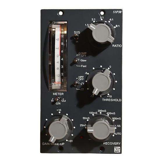
- Page 53 Rotary switch / knobs Install the ring nut for each rotary switch. [The original nut and shakeproof washers are not required]. Install the knobs as shown. 52F50 52F50 1.5:1 1.5:1 RATIO RATIO COMP COMP Slow Slow Fast Fast Rotate the switch shafts fully counter-clockwise...
- Page 54 Lid Insulator (Stops the pins of the output transformer shorting on the inside of the lid). 1] Remove the backing from the double sided tape on the lid insulator 2] Stick the insulator to the inside of the lid, just in front of the output transformer hole 3] After calibration, the lid can be secured in place using 4 x M3 button head screws.
- Page 55 Top Law 1.5:1 Audio Maintenance Limited E-Mail: service@audiomaintenance.com Title Comp Comp Ratio Ratio 52F50 - Block Diagram Initial Law Ground Number AML-07-137 Analogue Ground Date 11th Dec 2020 Drawn by C Adshead File AML-07-137 - rev5 Sheet 1 of 13...
- Page 56 Board A - Relay Power Solder these pads for 1mA meter Solder these pads for 0.5mA meter Audio Maintenance Limited E-Mail: service@audiomaintenance.com Title 52F50 - B192 Number AML-07-137 Date 11th Dec 2020 Drawn by C Adshead File AML-07-137 - rev5 Sheet 2 of 13...
- Page 57 J - B191 Switch Sub Ground H - B191 K - B191 L - B191 Audio Maintenance Limited E-Mail: service@audiomaintenance.com Title 52F50 - B191 Number AML-07-137 Date 11th Dec 2020 Drawn by C Adshead File AML-07-137 - rev5 Sheet 3 of 13...
- Page 58 Audio Maintenance Limited E-Mail: service@audiomaintenance.com Title 52F50 - B185 Number Jumper on = 5mS (Default) AML-07-137 Jumper off = 25mS Date 11th Dec 2020 Drawn by C Adshead File AML-07-137 - rev5 Sheet 4 of 13...
- Page 59 Audio Maintenance Limited E-Mail: service@audiomaintenance.com Title 52F50 - B183 Number AML-07-137 11th Dec 2020 Date Drawn by C Adshead File AML-07-137 - rev5 Sheet 5 of 13...
- Page 60 Audio Maintenance Limited E-Mail: service@audiomaintenance.com Title 52F50 - Comp Recovery Number Grayhill 6 Position switch - GR-03-003 AML-07-137 Pins at 12 O'Clock and 6 O'Clock positions Date 11th Dec 2020 Drawn by C Adshead File AML-07-137 - rev5 Sheet 6 of 13...
- Page 61 +7.5 +2.5 -2.5 Audio Maintenance Limited E-Mail: service@audiomaintenance.com Title 52F50 - Comp Threshold Number AML-07-137 Date 11th Dec 2020 Drawn by C Adshead File AML-07-137 - rev5 Sheet 7 of 13...
- Page 62 Audio Maintenance Limited E-Mail: service@audiomaintenance.com Title 52F50 - Gain Make-up Number AML-07-137 Date 11th Dec 2020 Drawn by C Adshead File AML-07-137 - rev5 Sheet 8 of 13...
- Page 63 1.5:1 Audio Maintenance Limited E-Mail: service@audiomaintenance.com Title 52F50 - Comp Ratio Number 1.5:1 AML-07-137 Date 11th Dec 2020 Drawn by C Adshead File AML-07-137 - rev5 Sheet 9 of 13...
- Page 64 Audio Maintenance Limited E-Mail: service@audiomaintenance.com Title 52F50 - Bypass Control Number AML-07-137 Date 11th Dec 2020 Drawn by C Adshead 10 of 13 File AML-07-137 - rev5 Sheet...
- Page 65 Relay 4 Power Output Meter Select Switch RL3 Out Relay 3 Power Input Audio Maintenance Limited E-Mail: service@audiomaintenance.com Title 52F50 - Meter Select Number AML-07-137 11th Dec 2020 Date Drawn by C Adshead AML-07-137 - rev5 11 of 13 File Sheet...
- Page 66 Fast Slow +24v Fused - Sub Board (8v) Audio Maintenance Limited E-Mail: service@audiomaintenance.com Title 52F50 - Comp Speed Switch Comp Speed Control Number AML-07-137 11th Dec 2020 Date Drawn by C Adshead AML-07-137 - rev5 File Sheet 12 of 13...
- Page 67 E-Mail: service@audiomaintenance.com -16v pin 14 - Board C (V Ref Negative) V Ref Negative Switch Sub Ground Title 52F50 - Power & Connects Number AML-07-137 Date 11th Dec 2020 Drawn by C Adshead File AML-07-137 - rev5 Sheet 13 of 13...
Need help?
Do you have a question about the Colourbook 52F50 and is the answer not in the manual?
Questions and answers