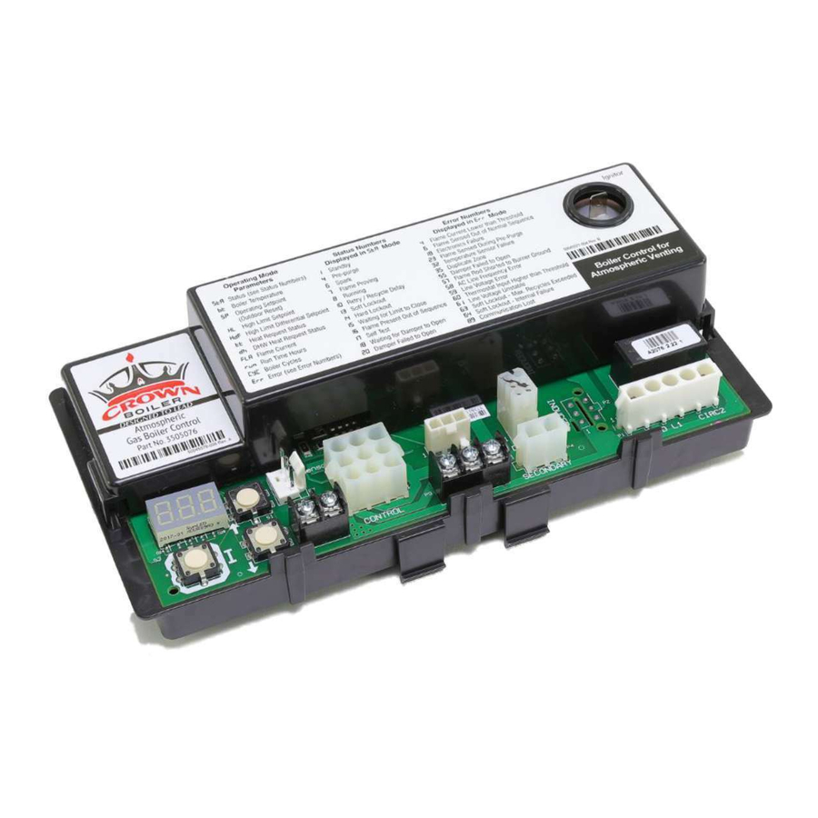
Advertisement
S9360A, S9361A,
S9380A, S9381A
Integrated Boiler Controllers
APPLICATION
These integrated boiler control modules provide ignition
sequence, flame monitoring and safety shutoff for
intermittent pilot spark ignition, or direct spark ignition
heating systems. They also provide limit rated water
temperature control with one or two sensors and display
interface capability for either "on-board" or remote user
interface applications.
• S9360A—Spark Ignition, Intermittent Pilot, Remote
Display.
• S9361A—Spark Ignition, Intermittent Pilot, "On board"
Display.
• S9380A—Direct Spark Ignition, Remote Display.
• S9381A—Direct Spark Ignition, "On board" Display.
• Enabled with EnviraCOM™ communication capability
to support remote monitoring and diagnostics.
• Limit-rated Temperature Sensing Probe.
• Ignitor sensor type
— two rod (separate ignitor and sensor)
— one rod (combined ignitor and sensor)
2012 DOE Compliance and Operation
Operation of this control may delay the burner operation while the residual heat is circulated
out of the boiler.
NOTE:
This operation may be different than earlier integrated boiler control
revisions which did not implement thermal purge.
INSTALLATION INSTRUCTIONS
SPECIFICATIONS
IMPORTANT:
The specifications given in this publication do
not include normal manufacturing tolerances.
Therefore, an individual unit may not match the
listed specifications exactly. Also, this product is
tested and calibrated under closely controlled
conditions, and some minor differences in
performance can be expected if those
conditions are changed.
Model Numbers
S—Switching Control
9 3—Integrated Hydronic Control Platform
6—Spark Ignition
8—Direct Spark Ignition
0—Remote Display Required
1—Integrated On-Board Display
A—Boiler Control
B—Water Heater Control
C—Pool Heater Control
1—No Circulator
2—On/Off Circulator
3—On/Off Circulator meeting CSD-1
66-1203-05
Advertisement
Table of Contents

Summarization of Contents
SPECIFICATIONS
Model Numbers
Lists the available integrated boiler controller model numbers and their configurations.
APPLICATION OVERVIEW
Integrated Boiler Controller Function
Describes the primary use of the controllers in heating systems.
Model-Specific Features
Details the specific features of each S9360A, S9361A, S9380A, S9381A model.
DETAILED SPECIFICATIONS
Electrical Ratings
Details the voltage, frequency, and current ratings for various components.
Flame Monitoring Parameters
Specifies timing and threshold parameters for flame detection and response.
Available Accessories
Lists optional accessories that can be purchased for the controllers.
COMPONENT AND INSTALLATION REQUIREMENTS
Controller Wells, Sensors, and Cables
Information on required wells, sensors, and ignition cables for installation.
Environmental Protection Guidance
Guidance on protecting controls from heat, moisture, chemicals, and dust.
INSTALLATION AND CHECKOUT
Critical Installation Warnings
Critical safety warnings regarding fire, explosion, and electrical shock hazards.
Preinstallation Safety Inspection
Requirements for pre-installation checks according to ANSI standard Z21.71.
Severe Environment Maintenance
Recommendations for maintenance in demanding environmental conditions.
Module Mounting Location
Instructions on selecting a mounting location and proper module placement.
WIRING GUIDELINES
Wiring Safety Precautions
Essential safety warnings before performing any wiring.
Ignition Cable Connection
Steps for connecting the ignition cable to the module and igniter.
Direct Spark Ignition Wiring
Specific wiring details for S938X DSI models.
Inducer and Gas Control Connections
Guidance for connecting inducer, gas control, and other system components.
STATE CODE DEFINITIONS
State Code Descriptions
Defines various operational states and their corresponding codes for the control module.
TEMPERATURE CONTROL AND DISPLAY
Temperature Control Operation
How the module controls boiler water temperature and its setpoint range.
On-Board Display Settings
Procedure for adjusting settings on models with an on-board display.
Display Readout Parameters
Explanation of the parameters shown on the module's display.
BOILER CONTROL AND CHECKOUT
Boiler Temperature Controller Logic
How the controller manages boiler water temperature and setpoints.
System Checkout Procedure
Steps to verify proper system operation after installation.
Sensing Bulb Location and Mounting
Guidance on installing the temperature sensing bulb and its location.
SENSOR INSTALLATION AND OPERATION MODES
Mounting Sensor and Thermowell
Detailed instructions for installing the temperature sensor in an immersion well.
High Limit Controller Functionality
How the high limit feature protects the system from over-temperature.
Thermal Purge Operation
Explanation of the thermal purge function to ensure residual heat circulation.
THERMAL PURGE SETTINGS AND SEQUENCE
Thermal Purge Parameter Settings
Minimum, maximum, and default values for thermal purge settings.
Operating Sequence Diagram
Visual representation of the control module's operational steps and states.
TROUBLESHOOTING IGNITION SYSTEMS
General Troubleshooting Tips
Important guidelines and procedures for troubleshooting ignition issues.
Intermittent Pilot Ignition Checks
Step-by-step checks for ignition cable, grounding, and spark circuit.
Pilot and Main Burner Lightoff
Procedures for verifying proper pilot and main burner ignition and flame.
Troubleshooting Error Codes
Introduction to error codes and their meanings for diagnostics.
ERROR CODE DEFINITIONS
Specific Error Code Explanations
Detailed definitions for various error codes displayed by the control module.


Need help?
Do you have a question about the S9381A and is the answer not in the manual?
Questions and answers