Table of Contents
Advertisement
Quick Links
Advertisement
Table of Contents

Related Manuals for D.W. Fearn LP-1


Summary of Contents for D.W. Fearn LP-1
- Page 1 HAZELRIGG INDUSTRIES Vacuum Tube Preamplifier/EQ/DI Operating Instructions...
- Page 2 How to Contact us: Telephone: 567-DW FEARN (567-393-3276) Shipping Address: 124 Tartan Terrace Chalfont, PA 18914 U.S.A. e-mail: support@hazelriggindustries.com www.dwfearn.com VLC Microphone Preamplifier/EQ/DI HAZELRIGG INDUSTRIES...
- Page 3 124 Tartan Terrace Chalfont, PA, U.S.A. Tel: 567-393-3276 Certificate of RoHS Compliance D.W. Fearn / Hazelrigg Industries is committed to manufacturing products that are fully- compliant with the EU RoHS Directive. The following products are compliant: VT-1, VT-2, VT-24, VLC(-1)
- Page 4 VLC Vacuum Tube Microphone Preamplifier Final Test Report Serial Number Mains Voltage: Date Tested by THD+Noise: Equalizer: 20 cps LF Cut 200 cps LF Boost 2 kc/s HF Boost 20 kc/s HF Cut Operational Tests: Listening Test +48V -20 pad...
-
Page 5: Table Of Contents
Table of Contents Warranty....................6 Specifications....................7 Description....................8 Installation....................9 Operation....................12 Theory......................18 Maintenance ....................20 List of Illustrations Rear Panel Connections................11 Front Panel Controls and Connections.............13 VLC Microphone Preamplifier/EQ/DI HAZELRIGG INDUSTRIES... -
Page 6: Warranty
This warranty does not extend to any VLC that has been damaged or rendered defective as a result of accident, misuse, or abuse; by the use of parts not manufactured or supplied by D.W. -
Page 7: Specifications
-124 dbm maximum Output low-Z, transformer balanced Maximum Output Level +22 dBm unterminated Power Requirements 120 or 220 VAC 50/60Hz, 25 W Dimensions 19” (48.26cm) W 3.5” (13.34cm) H 14” (22.86cm) D Weight 12.5 lbs. (5.66 kg) VLC Microphone Preamplifier/EQ/DI HAZELRIGG INDUSTRIES... -
Page 8: Description
It is typically used in sound recording studios for recording individual tracks. A quality microphone is connected to a VLC input, and the VLC provides a line-level output. In most situations, the VLC will feed directly to the input of the recorder. -
Page 9: Installation
In tight equipment enclosures, be sure there is adequate air flow. Forced air cooling will benefit all your equipment. The VLC can also be used without a rack, placed on a table, counter, or even on the floor. Optional rubber feet are available, when requested at the time of the order. - Page 10 The AC input connector is used with the mating line cord (supplied). For 115 VAC operation, this cord is a Belden 17250 or equivalent. The unit does not utilize any RFI filtering, and no RFI has been experienced, even when the VLC is operated in close proximity to AM, FM, and TV broadcast transmitters.
-
Page 11: Rear Panel Connections
Figure 1. The VLC rear panel connectors All connectors are wired according to AES standard: pin 1 is ground (shield), pin 2 is “high” or “+,” and pin 3 is “low” or “-.” A positive voltage on pin 2 of the input will result in a positive voltage on pin 2 of the output (with the Phase Reverse switch set to Normal). -
Page 12: Operation
VLC input. This can be achieved with a dedicated line from an XLR connector in the studio to each VLC in the control room. Although long input cable runs have little effect on the performance of the VLC, it is preferable to keep the input line as short as possible. -
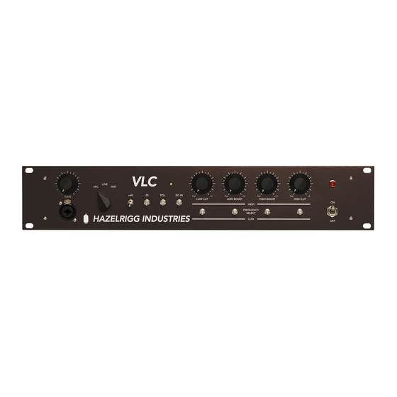
Page 13: Front Panel Controls And Connections
(if it has one), the VLC -20 switch position, or both. Let your ears be the judge. Slight to moderate overdriving of the VLC often adds “edge,” “power,” or “excitement” to the sound. - Page 14 The phantom power circuit used in the VLC is suitable for use with all Neumann micro- phones, AKG 12 and 48 volt microphones, B&K phantom powered mics, all Schoeps mics, Shure SM81 and 85 mics, Crown PZM mics, and virtually all other phantom-powered mics that require any voltage between 12 and 48 volts.
- Page 15 VLC pad should be determined by experimentation. For the cleanest sound it is generally preferable to pad at the microphone first, then at the VLC if necessary. The sound of some microphones will change slightly with the -20 position. This is a function of the interaction between the microphone transformer and the VLC input transformer.
- Page 16 Power switch and indicator (12 & 11) Primary power is applied to the VLC circuits when the Power switch (12) is in the up position. The red pilot lamp (11) indicates that the unit is on. It take about twenty seconds for the preamp to start working, but it is suggested that you turn on the power at least five minutes prior to use.
- Page 17 If necessary, use the POL reverse switch. The +48 switch should be off except when needed for phantom powered microphones. The best indication of proper operation of the VLC is how it sounds. This preamplifier has a wide operating range and quite often the exact position of the controls is relatively non-critical.
-
Page 18: Theory
Output Stage The output stage operates as a cathode follower, presenting a comparatively low output impedance (approximately 800 ohms). Equalization Section The passive LC (inductor/capacitor) equalization is inserted at the mic preamp output. VLC Microphone Preamplifier/EQ/DI HAZELRIGG INDUSTRIES... - Page 19 VLC. The power transformer is a toroidal unit custom-made for the VLC and has primary taps for 115 and 220-240 volt operation. A switch on the rear makes it quick and easy to go between voltages. Be sure to also change the fuse to the appropriate value.
-
Page 20: Maintenance
Vacuum Tubes Four 6072A tubes are used in the VLC. There can be as much as a 15 dB difference in noise level among an assortment of tubes, and the tubes used in the first position should be carefully chosen to maintain low noise. - Page 21 Call first, however, for shipping information. WARRANTY REPAIR If the VLC should develop a problem during the 7-year warranty period, call the factory for return shipping instructions. We will repair and return your VLC quickly. Note that the warranty does not cover vacuum tubes, which must be periodically replaced.
Need help?
Do you have a question about the LP-1 and is the answer not in the manual?
Questions and answers