Advertisement
Quick Links
Advertisement

Related Manuals for D.W. Fearn VT-12


Summary of Contents for D.W. Fearn VT-12
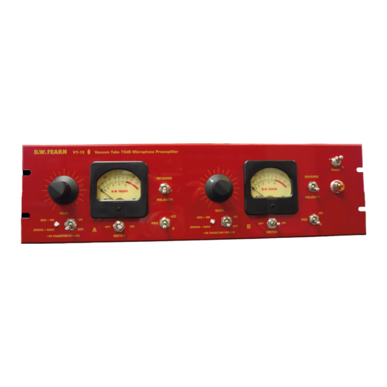
- Page 1 D.W. FEARN VT-12 Vacuum Tube 70dB Microphone Preamplifier Operating Instructions...
- Page 2 How to Contact us: Telephone: 610-793-2526 Fax: 610-793-1479 Mail: P.O. Box 57, Pocopson, PA 19366 U.S.A. Shipping Address: 182 Bragg Hill Road West Chester, PA 19382 U.S.A. e-mail: dwfearn@dwfearn.com www.dwfearn.com D.W. FEARN VT-12 Microphone Preamplifer...
- Page 3 Pocopson, PA 19366 U.S.A. PROFESSIONAL Tel: 610-793-2526 RECORDING EQUIPMENT www.dwfearn.com Fax: 610-793-1479 Certificate of RoHS Compliance D.W. Fearn is committed to manufacturing products that are fully-compliant with the EU RoHS Directive. The following products are compliant: VT-1 VT-12 VT-3 VT-4...
- Page 5 VT-12 Vacuum Tube Microphone Preamplifier Final Test Report Model _______________ Serial Number_______________Mains Voltage: 100 120 240 Date ___________________ Tested by ________ Assembled by _____________________ Test Equipment ____________________________ Microphone ________________________ Channel B Channel A Frequency Response: Frequency Response: 20 cps to 20 kc/s +/- ___________ dB...
-
Page 6: Table Of Contents
LP-1 Line Pad Instructions ............37 List of Illustrations 1. Rear Panel Connections ............18 2. Front Panel Controls and Indicators ........21 3. Typical Studio Interconnections ..........27 4. Block Diagram ................30 5. Location of VU Meter Calibration ...........35 D.W. FEARN VT-12 Microphone Preamplifer... - Page 7 D.W. Fearn shall not be liable for technical or editorial errors or omissions in this manual, nor for incidental or consequential damages resulting from the use of this material. This instruction manual contains information protected by copyright. No part of this manual may be photocopied or reproduced in any form without prior written consent from D.W.
-
Page 8: Warranty
During the warranty period, D.W. Fearn will, at no additional charge, repair or replace defective parts with new parts. This warranty does not extend to any VT-12 that has been damaged or rendered defective as a result of accident, misuse, or abuse; by the use of parts not manufac- tured or supplied by D.W. - Page 9 Could that sound be duplicated today? I dug out my old RCA Receiving Tube Manual and several other old reference books and reviewed the vacuum tube theory I hadn’t thought about for years. A quick check in the supplier’s catalogs confirmed that tubes were still easy to obtain. D.W. FEARN VT-12 Microphone Preamplifer...
- Page 10 It’s the nature of the distortion that makes a difference, too. Solid state circuits run out of headroom when the output voltage exceeds the power supply voltage. The result at this point D.W. FEARN VT-12 Microphone Preamplifer...
- Page 11 AB comparison of the sound, I am certain that the better modern passive components give the VT-1 a superior sound. The VT-1 has been used for all types of recording — vocals, announcers, acoustic instruments, electric instruments, classical — and it works well with them all. D.W. FEARN VT-12 Microphone Preamplifer...
- Page 12 1/VT-12 were often used with ribbon mics, the 54dB of gain in the stock VT-1/VT-12 was not quite enough for some situations. We developed a simple mod that added 6dB of gain to the VT-1 or VT-12, and that was enough to make ribbon mics useable in almost all situations.
-
Page 13: Specifications
Output Level +22 dBm unterminated Power Requirements 100, 120, or 220 VAC 50/60Hz, 25 W Dimensions 19” (48.26cm) W 5.25” (13.34cm) H 13” (22.9cm) D Weight VT-12 18 lbs (8.16kg) Shipping Weight 24 lbs (10.9kg) D.W. FEARN VT-12 Microphone Preamplifer... -
Page 14: Description
A quality ribbon microphone is connected to a VT-12 input, and the VT-12 provides a line-level output. In most situations, the VT-12 will feed directly to the input of the recorder. -
Page 16: Installation
Be sure the bottom vent slots are not blocked. It is essential that air can flow into the bottom and out of the top of the VT-12. Equipment that runs cool can last for a very long time. A 1RU vented panel, the D.W. Fearn VRP painted in the same red as our products is available. - Page 17 Power The VT-12 is designed to operate from 100, 120, or 220-240 volt, 50/60 Hz power. The unit will be shipped set for the voltage specified in the order, but may be changed in the field if necessary. A rear-panel, recessed slide switch changes the input voltage for either 120V or 230V.
- Page 18 The shield should be connected to ground at only one end of the output cable; however, although not recommended, the shields can often be connected at both ends with- out a problem. D.W. FEARN VT-12 Microphone Preamplifer...
- Page 19 D.W. FEARN VT-12 Microphone Preamplifer...
- Page 20 One successful method is to place the VT-12 in the studio with only a short cable to the microphone. Line level from the VT-12 output is then fed back to the con- trol room. Avoid locating the VT-12 where it will be subjected to high sound levels or exces- sive vibration (such as on a drum riser).
- Page 21 Note that some ribbon mics (“active ribbons”) may require phantom power to operate the electronics in the microphone. Also note that active ribbon mics have an output level much higher than a standard ribbon mic and may require the use of the -20 pad on the VT-12 to prevent overload.
- Page 22 Power switch and indicator Primary power is applied to the VT-12 circuits when the Power switch (8) is in the up posi- tion. The amber pilot lamp (7) indicates that the unit is on. It takes about twenty seconds for the preamp to start working, but it is suggested that you turn on the power at least five min- utes prior to use.
- Page 23 In some situations, the Gain control can have an effect on VT-12 distortion, but at +4 dBm output the input stages will overload before the output. If you find that you need to run the...
- Page 24 This is the standard “0 VU” level for all professional audio recording equipment built since the early 1970s. “0 VU” on the VT-12 should result in “0 VU” on a properly aligned recorder. (This reference level can be changed; see the Maintenance Section.) This is a true VU meter, and conforms to ASA Standard C16.5-1954.
- Page 25 (See Section 6 - Maintenance.) SUGGESTIONS: You have chosen to use the VT-12 because of the superior sound it provides. To gain the max- imum benefit from your investment, it is important that you hook up the VT-12 so that other factors do not adversely affect the sound quality.
- Page 26 4. The output of the VT-12 should be fed directly to the recorder through the shortest practical length of quality cable. Avoid additional cables, connectors, junction boxes, punch blocks, or patch jacks. Use gold contact connectors if possible. Do not go through the mixing console unless you absolutely need its features for the track you are cutting.
- Page 27 D.W. FEARN VT-12 Microphone Preamplifer...
-
Page 28: Theory Of Operation
In the Normal position, input/output phase (polarity) is maintained (which must be inverted due to the design of the circuit). The balanced output is polarity reversed in the Reverse posi- tion. Switching is accomplished with a sealed, gold-contact instrumentation relay with bifur- cated contacts. D.W. FEARN VT-12 Microphone Preamplifer... - Page 29 Input transformer The input transformer is custom-made for D.W. Fearn by Jensen Transformers, Inc. and rep- resents the state of the art in transformer design. It exhibits extremely flat frequency response, low phase shift, excellent square wave response, low distortion, and high noise immunity.
- Page 30 The Power switch energizes all four power supplies. A fuse, accessible on the rear panel, protects the VT-12. The Pilot lamp is a type 1819 bulb, operated far below its rated voltage of 28. The life of the bulb is lengthened, and the light output is more compatible with other modern studio equipment.
- Page 31 This regulator is located on the Power Supply PCB. B+ Supply Two separate regulated voltages are required for the plates of the VT-12. The B+ is filtered with long-life, low-leakage, computer-grade filter capacitors before being regulated and exten- sively bypassed and decoupled.
-
Page 32: Maintenance
VT-12). Vacuum Tubes Four 12AT7 tubes are used in the VT-12. V101 and V201 are the input stage and V102 and V202 are the output stages. There can be as much as a 15 dB difference in noise level among an assortment of tubes, and the tubes used in the V101 and V201 positions should be care- fully chosen to maintain low noise. - Page 33 Electrolytic Capacitors The VT-12 is designed and built to last for a long, long time, and it is possible that some com- ponents (e.g. electrolytic capacitors) may reach the end of their life long before the equip- ment becomes obsolete. The electrolytic capacitors used in the VT-12 typically will last at least twenty years.
- Page 34 If you lack access to a qual- ified service technician with vacuum tube equipment repair experience, you may return the VT-12 to the factory for repair. Call first, however, for shipping information. An RMA form is available on our web site, under “Support.”...
- Page 35 D.W. FEARN VT-12 Microphone Preamplifer...
- Page 36 The LP-1 Line Pad is an accessory for the VT-1, VT-2, and VT-12 Vacuum Tube Microphone Preamplifiers that allows the preamp to accommodate a line-level signal of approximately +4 dBm. This is used when it is necessary for the VT-12 to process a line-level signal, such as in final processing of a mix.
Need help?
Do you have a question about the VT-12 and is the answer not in the manual?
Questions and answers