
Related Manuals for Omniflex Omni16C Series

Summarization of Contents
2 General Description
2.1 Standard Features
Details standard features of Omni8/16C units for alarm annunciator systems.
2.2 Options Available
Lists optional features and accessories for Omni8/16C units.
2.3 Product Feature Chart
Provides a comprehensive chart of features for various Omni8/16C product models.
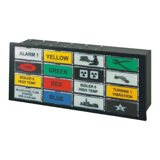
2.4 Front Views of Panel Mount Units
Shows front views and numbering layout for Omni8C, Omni16C, and Omni8P units.
2.7 Rear View of Omni16C Units
Details the terminal layout on the rear of Omni16C 16-point units.
2.8 Rear View of Omni8C Units
Details the terminal layout on the rear of Omni8C 8-point units.
2.9 Rear View of Omni8P Units
Details the terminal layout on the rear of Omni8P 8-point units.
3 Mechanical Installation
3.1 Panel-mount Mechanical Dimensions
Provides dimensions and cut-out details for panel mounting Omni8/16C units.
3.2 Wall-mount Mechanical Dimensions
Details dimensions for wall-mounting Omni16C and Omni8C/16C units.
3.3 Introduction to Panel Mounting
Introduces panel mounting methods for Omni8/16C units, including single and multiple units.
3.4 Panel Mounting Multiple Units
Explains procedures for mounting multiple Omni8/16C units in a single panel cut-out.
3.5 Mounting a Single Omni8/16C
Specifies the panel cut-out required for mounting a single Omni8/16C unit.
3.6 Intrinsically-Safe Annunciator Mounting
Covers installation requirements for intrinsically-safe Omni16C EX units.
3.7 IP65 Front Cover Mounting
Details the mechanical mounting of IP65 front covers for environmental protection.
3.8 Internal Pushbutton Station Installation
Guides the installation of the optional integral pushbutton station into the unit.
3.9 Back-lit LED Board Installation
Provides instructions for installing backlit LED boards into the display windows.
3.10 Back-lit LED Board Removal
Offers guidance on safely removing backlit LED boards from the unit.
3.11 Creating Window Legends
Explains how to create legend films for backlit display windows using software templates.
3.12 Inserting Legends and Colour Filters
Details inserting legends and optional colour filters into backlit display windows.
3.13 Sidebar Display Window Legends
Describes creating legends for sidebar LED display windows using engraved plastic.
4 ELECTRICAL INSTALLATION
4.1 Introduction
Introduces electrical connections to Omni8/16C units and available block diagrams.
4.2 Omni8C Block Diagram
Presents a block diagram of the Omni8C annunciator showing terminal connections.
4.3 Omni8P Block Diagram
Presents a block diagram of the Omni8P annunciator showing terminal connections.
4.4 Omni16C Block Diagram
Presents a block diagram of the Omni16C annunciator showing terminal connections.
4.5 Intrinsically Safe Omni16C-Ex Block Diagram
Shows the block diagram for the intrinsically safe Omni16C-Ex model.
4.6 Terminal Schedule
Provides a detailed terminal schedule for connecting Omni8C/8P/16C units.
4.7 Serial Port Pinouts
Details the pinouts for serial port connections to PC or PLC.
4.8 Power Requirements
Lists power consumption for various Omni8/16C models and options.
4.9 Connecting the Power Supply
Guides on connecting external and internal power supplies to Omni8/16C units.
4.10 Connecting Alarm Inputs
Explains how to connect alarm inputs using potential free contacts and optional cards.
4.11 Connecting Common Service Relay Contacts
Details the connection of common service relay contacts for outputs.
4.12 Connecting Control Pushbuttons
Guides on connecting internal and external pushbuttons for controlling the unit.
4.13 Connecting Remote Pushbutton Station
Explains how to connect a remote pushbutton station to Omni8/16C units.
4.14 Connecting Omni8P Internal Audible Device
Details connecting the Omni8P's internal audible warning device.
4.15 Connecting Omni8P Audible to other Omni8/16C's
Explains how to connect the Omni8P audible device to other Omni8/16C units.
4.16 Connecting C1169 Lamp Driver Board
Details connecting the optional C1169 Lamp Driver board outputs.
4.17 Connecting the Inhibit Input
Explains how to connect the inhibit input to prevent new alarms.
4.18 Connecting Input Repeat Relay Contacts
Guides on connecting optional input repeat relay contacts (Model C1425).
4.19 Connecting Ribbon Header Outputs
Details connecting optional ribbon header outputs (Model C1426).
4.20 Synchronising Flashing Between Units
Explains how to synchronise flashing between multiple Omni8/16C units.
4.21 Expanding First-Out Groups
Describes expanding First-Out groups across multiple Omni8/16C units.
4.22 Electrical Installation for Intrinsically Safe Annunciators
Outlines electrical installation requirements for intrinsically safe Omni16C annunciators.
5 Configuring the Omni8/16C for Operation
5.1 Introduction
Introduces configuration via set-up switches and their grouping.
5.2 Modes of Operation
Explains the two operating modes: SWITCH-SET and SOFT-SET.
5.3 Selecting the Input Sense
Details setting input sense (normally open/closed) using set-up switches.
5.4 Selecting Alarm/Display Logic Sequences
Guides on selecting alarm/display logic sequences using SW1 and SW2 settings.
5.5 Selecting Group Alarm Relay Output Function
Explains how to select the function of the Group Alarm Relay (RL3).
5.6 Selecting Inhibit Input Contact Sense
Details selecting the inhibit input contact sense using SW2-6.
5.7 Selecting the Lamp Status
Explains how to select lamp status display (NORMAL/REVERSE) using SW2-8.
5.8 Selecting Time Delays
Guides on setting time delays for alarm sequences using SW2-1 to SW2-5.
5.9 Selecting Serial Port Settings
Details how to configure serial port settings (Modbus address, baud rate) using DIP switches.
5.10 Changing Repeat Output Operation
Explains how to change the operation of Repeat Output relays.
6 Operation
6.1 Power up
Describes the unit's power-up sequence, including self-test routines.
6.2 Normal Operation
Explains how the unit operates during normal alarm conditions and operator interaction.
6.3 Test Functions
Details the lamp test and circuit test functions, including fault indication.
6.4 Use of the Inhibit Input
Explains how to use the inhibit input to disable new alarms.
7 FUNCTIONAL SAFETY MANUAL
7.1 Function Specification
Defines the Omni16C's function as an alarm annunciator for safety-critical applications.
7.2 Hardware Configuration
Lists hardware modules required for SIL1 certification of the Omni16C.
7.3 Installation Requirements
Outlines installation, configuration, and operation requirements for maintaining performance.
7.4 Functional Safety Parameters
Describes functional safety parameters, failure definitions, and detected failures.
7.5 Diagnostics
Explains methods used to indicate internal failures detected within the unit.
7.6 Proof Test
Details the procedures for performing circuit tests and full proof tests.
7.7 Prevention of Systematic Failures
Provides guidelines to prevent systematic failures due to incorrect connection or configuration.
8 SPECIFICATIONS
Power Supply Options
Lists voltage options, isolation, ripple, and current consumption for power supplies.
Non-Isolated Alarm/Display Inputs
Details specifications for non-isolated alarm/display inputs, including type, voltage, and scan rate.
Isolated Alarm/Display Inputs
Details specifications for isolated alarm/display inputs, including voltage, isolation, and quantity.
Alarm Sequences Specifications
Lists the quantity and types of user-selectable alarm sequences.
Flash Rates
Specifies the fast and slow flash rates for alarm indications.
Integral Pushbuttons Specifications
Details the quantity, type, and functions of integral pushbuttons.
Window Display Specifications
Describes types, sizes, and legend types for window displays.
Common Service Relay Outputs
Specifies contact type, rating, and isolation for common service relay outputs.
Optional Repeat Relay Outputs
Specifies contact type, rating, and isolation for optional repeat relay outputs.
Temperature and Humidity
Lists operating and storage temperature ranges, and humidity recommendations.
Weight Specifications
Provides unpacked and packed weight specifications.
Compliance to Standards
Lists compliance with safety and EMC standards.
9 ALARM SEQUENCE DIAGRAMS
Sequence 1 - Lamp Follows Input
Diagram showing alarm sequence where lamp state follows input state.
Sequence 2 - Momentary Alarm, Manual Reset
Diagram for momentary alarm with manual reset and timer option off.
Sequence 2 - Momentary Alarm, Manual Reset, Time Delay
Diagram for momentary alarm with manual reset and time delay.
Sequence 3 - Alarm Only, Auto Reset
Diagram for alarm-only sequence with auto reset and timer option off.
Sequence 3 - Alarm Only, Auto Reset, Time Delay
Diagram for alarm-only sequence with auto reset and time delay.
Sequence 4 - Momentary Alarm, Manual Reset, Ringback
Diagram for momentary alarm with manual reset and ringback, timer off.
Sequence 4 - Momentary Alarm, Manual Reset, Ringback, Time Delay
Diagram for momentary alarm with manual reset, ringback, and time delay.
Sequence 5 - Momentary Alarm, First Out Multiple Groups
Diagram for momentary alarm with first out, multiple groups, manual reset, ringback.
Sequence 6 - Momentary Alarm, First Out Manual Reset
Diagram for momentary alarm with first out, manual reset, auto reset on subsequent alarms.
Sequence 21 - Momentary Alarm, First Out Multiple Groups, Auto Reset
Diagram for momentary alarm, first out multiple groups, auto reset.
Sequence 23 - Momentary Alarm, First Out Single Group, Auto Reset
Diagram for momentary alarm, first out single group, auto reset, continuous flash.
Sequence 24 - Momentary Alarm, First Out Multiple Groups, Auto Reset
Diagram for momentary alarm, first out multiple groups, auto reset, no horn for subsequent.
Sequence 25 - Momentary Alarm, Auto Reset, Auto Silence
Diagram for momentary alarm, auto reset, auto silence after time delay.
Sequence 26 - Momentary Alarm, Auto Reset, Re-alarm
Diagram for momentary alarm, auto reset, re-alarm after time-out.
Sequence 27 - Momentary Alarm, Auto Reset, Motor Alarms
Diagram for momentary alarm, auto reset, motor alarms, timer option off.
Sequence 27 - Momentary Alarm, Auto Reset, Motor Alarms, Time Delay
Diagram for momentary alarm, auto reset, motor alarms, time delay.
Sequence 29 - Pulse Monitoring Alarm
Diagram for pulse monitoring alarm with auto reset.
10 MODBUS REGISTER LAYOUT
Modbus Function Overview
Lists supported Modbus functions for communication with Omni8/16C.
Product Information Registers
Details registers for product code, revision, kernel version, and services.
User Tag and Alive Counter Registers
Describes registers for user-defined tags and the alive counter.
Status Data Registers
Covers registers for input status, common service output status, and lamp status.
Common Service Input Status Registers
Details registers for common service input status and control.
Alarm and Lamp Status Registers
Describes registers for alarm status and lamp status reporting.
Fault Status Register
Details the register for reporting unit fault status and error codes.
Setup Data Registers
Covers registers for setting sequence numbers for inputs.
Setup Timer Setting Registers
Details registers for configuring input timer settings.
Setup Lamp Sense and First Out Group Split
Covers registers for setting lamp sense and splitting first-out groups.
Setup System Operation and Slow Timer
Details registers for system operation settings and slow timer configuration.
Setup Common Relay Operation
Describes registers for configuring common relay operations for horn and group alarms.
Setup Repeat Relay GA Operation
Details registers for configuring repeat relay operations for group alarms.
Setup Common Relay Input Members
Covers registers for mapping inputs to common relays.
Setup Repeat Relay Input Members
Covers registers for mapping inputs to repeat relays.
Setup Modbus Extended Slave Address
Details the register for setting the Modbus extended slave address.
Need help?
Do you have a question about the Omni16C Series and is the answer not in the manual?
Questions and answers